Build Redux
Liquid Cooler Replacement Guide
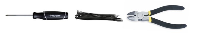
STEP 1: We will need a Phillips head screwdriver, wire cutter and 10-15 medium sized zip ties.
STEP 2: Move the system to a position where it is free of obstructions and easy to access.
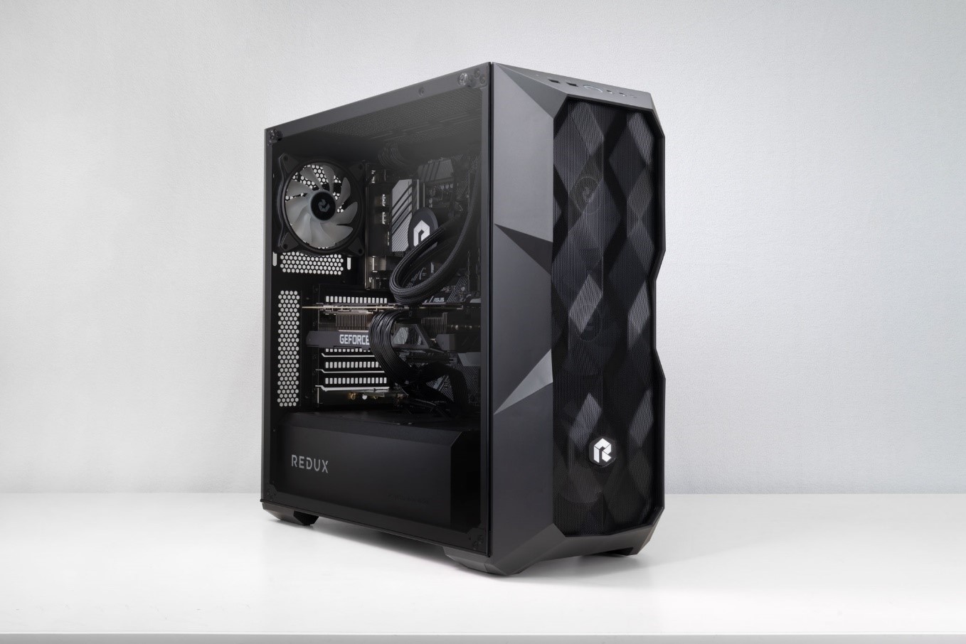
Make sure you have easy access to the side of your PC. Leaning over or around items on your desk will make the process much more difficult.
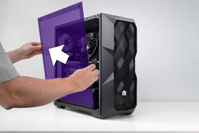
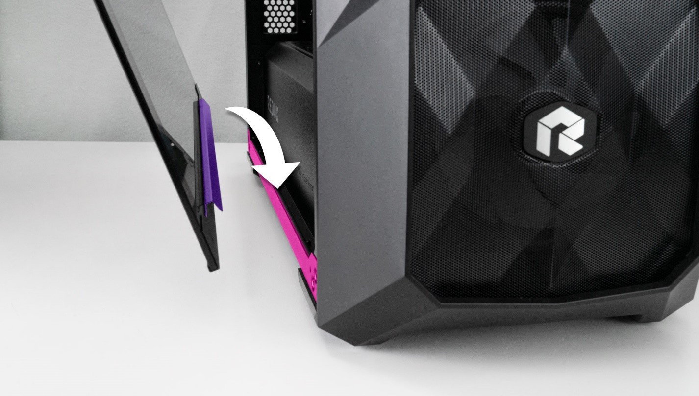
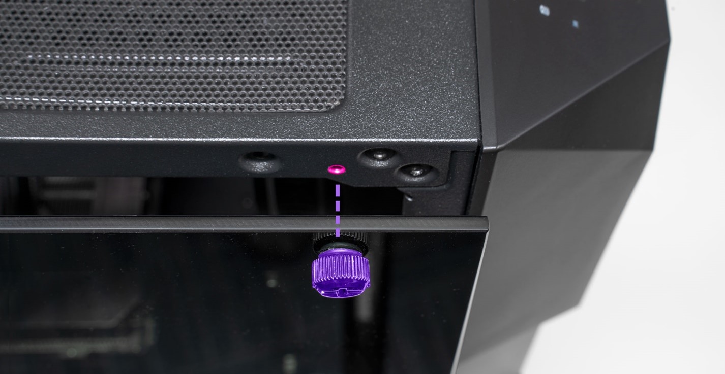
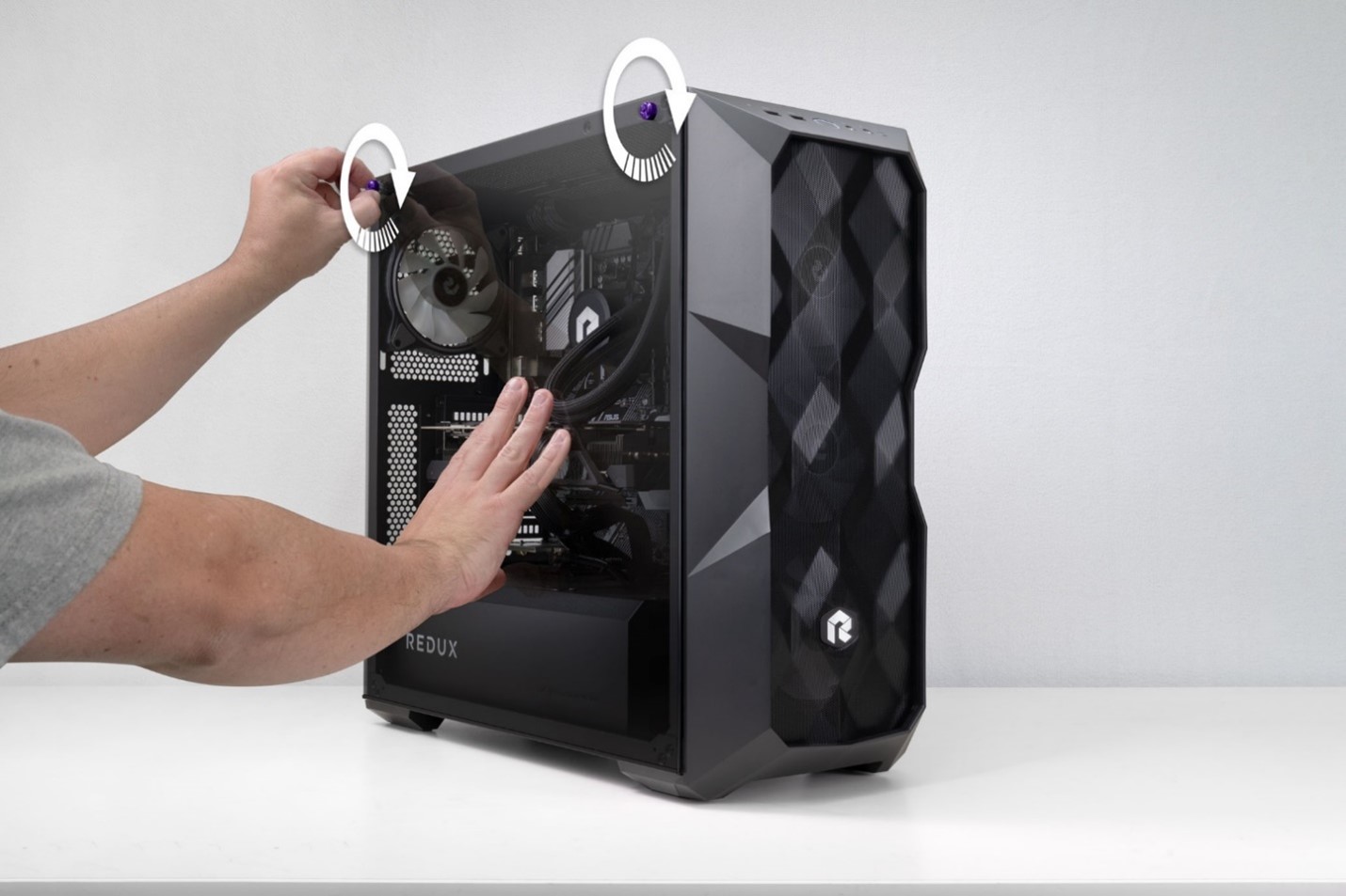
STEP 3: Gently hold the Glass panel to the case with one hand while unscrewing the 2 thumb screws until they are loose from the case. You don’t need to remove the screws from the glass.

As seen above hold the glass with one hand while removing the screws. The glass sits on a bracket at the bottom of the case and should stay in place without falling over. It’s still good to brace the glass with your hand as a safety precaution.
Screws are imbedded in glass. Don’t remove screws from glass panel.

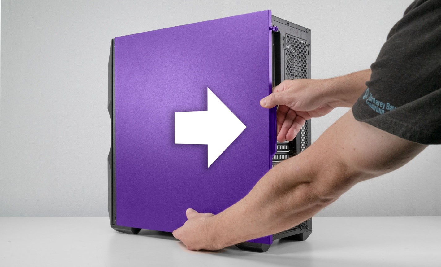
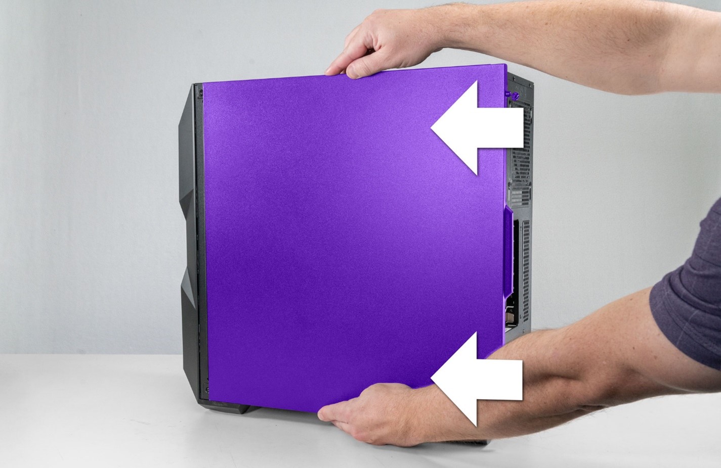
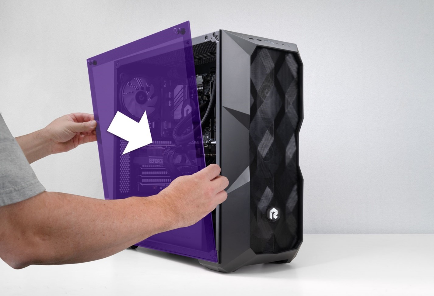
STEP 4: Grab the glass panel firmly with both hands. Pull it away from the PC and gently set it aside.
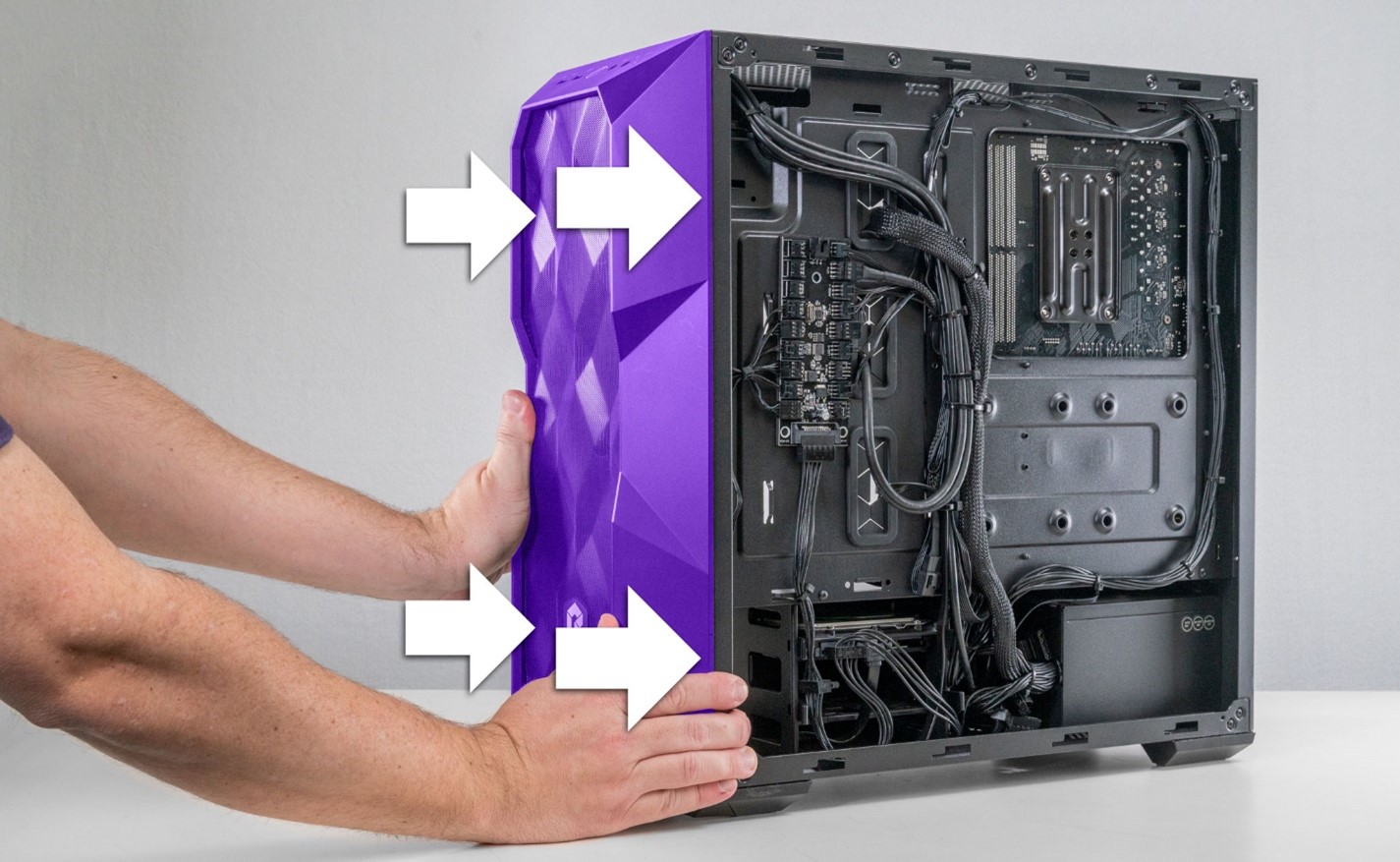
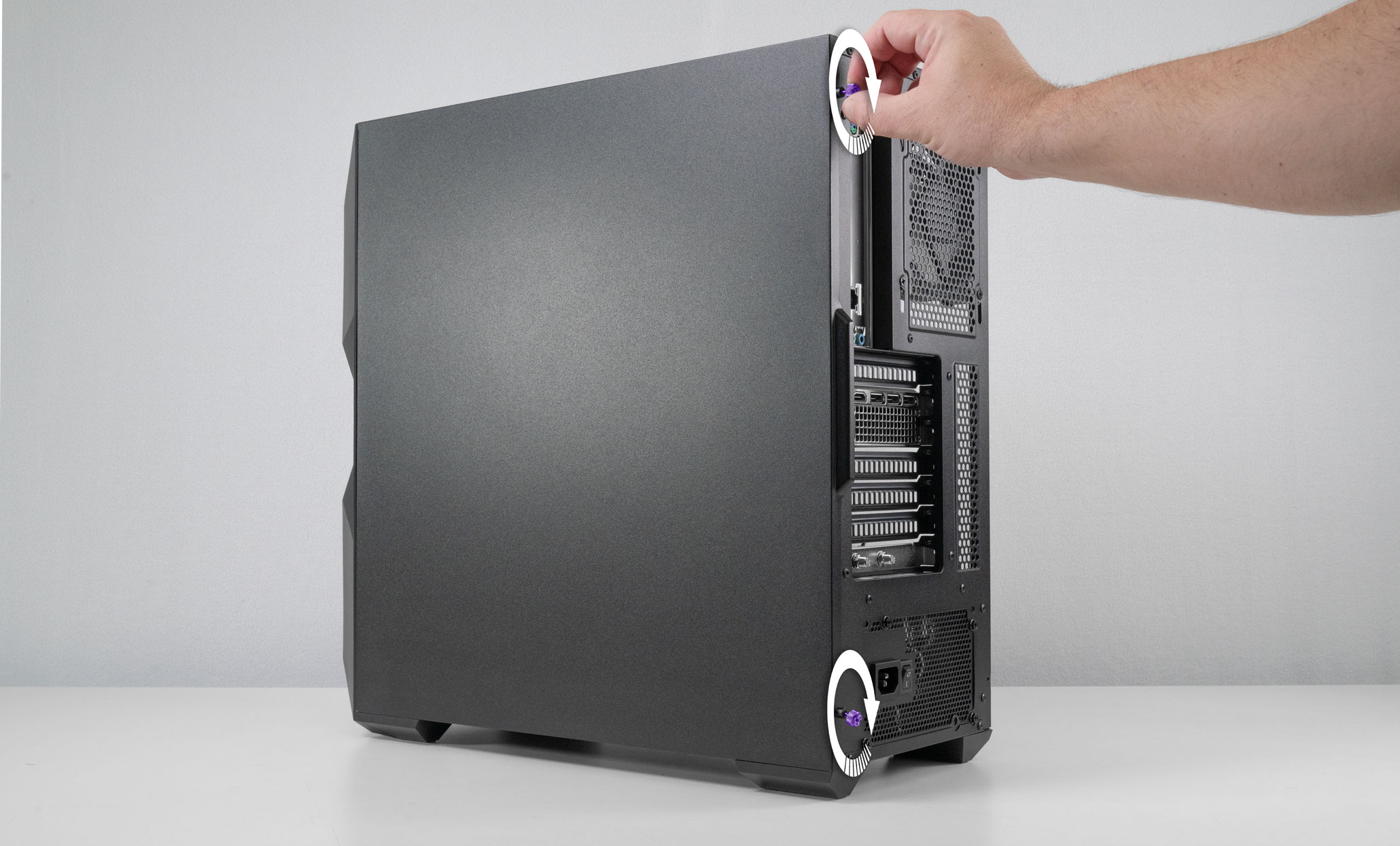
STEP 5: We need to remove the case back panel as well. Move to the other side of the system and unscrew the 2 thumb screws.

STEP 6: Grab the handle along the back panel of the system with one hand and brace the bottom of the panel with your other hand. Gently pull back on the panel with both hands until the panel comes off.
Set the panel aside somewhere safely out of the way.
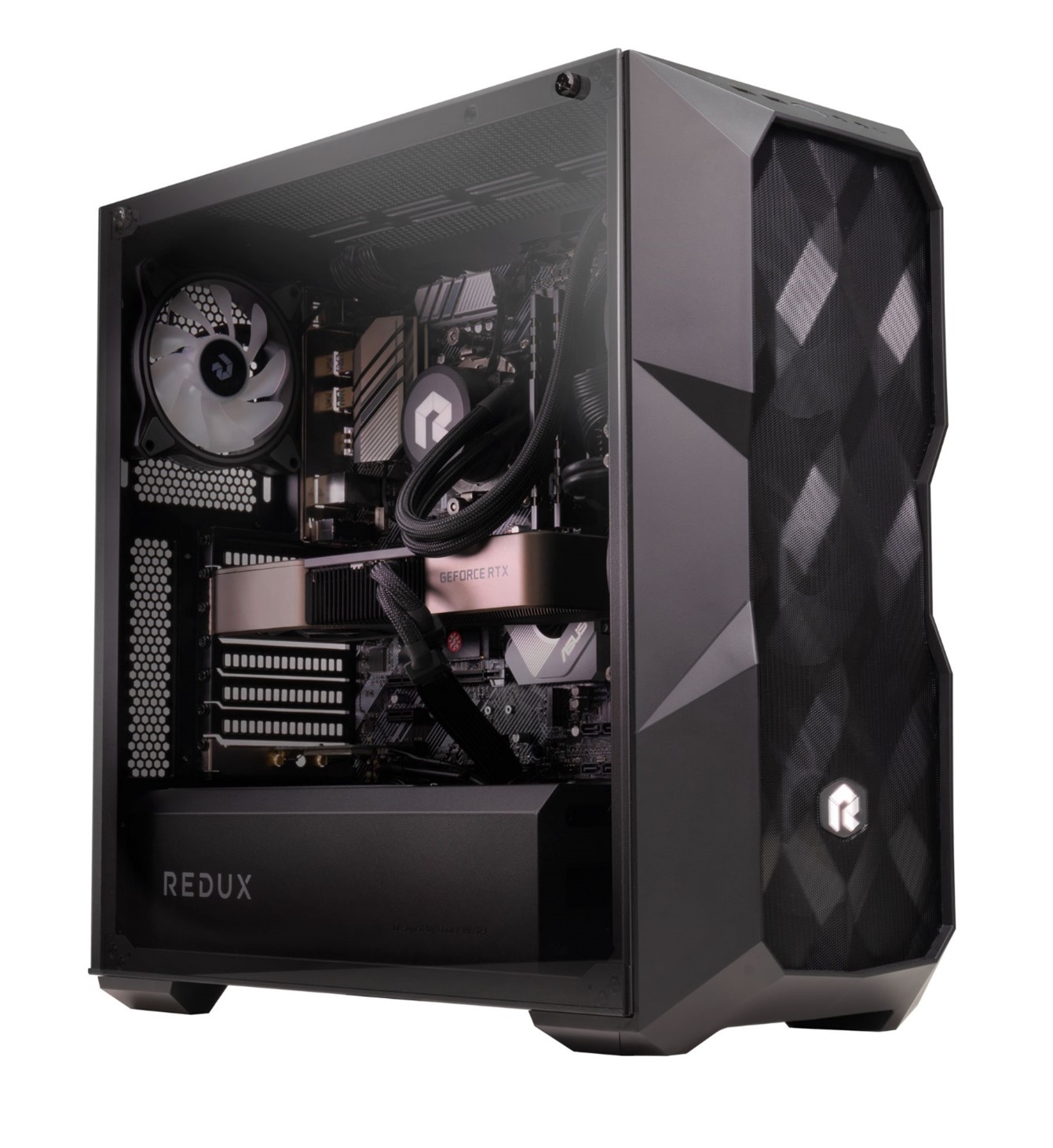
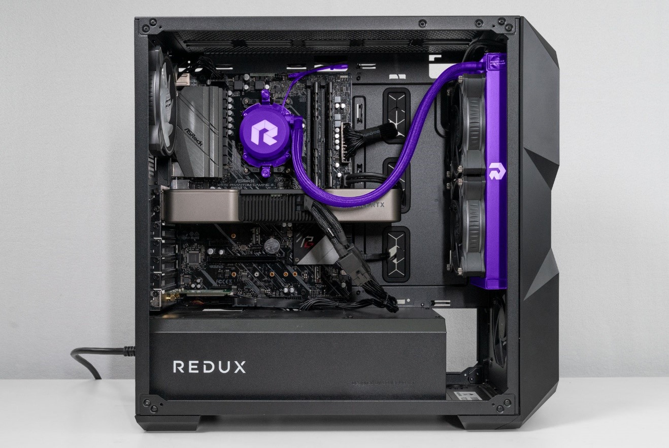
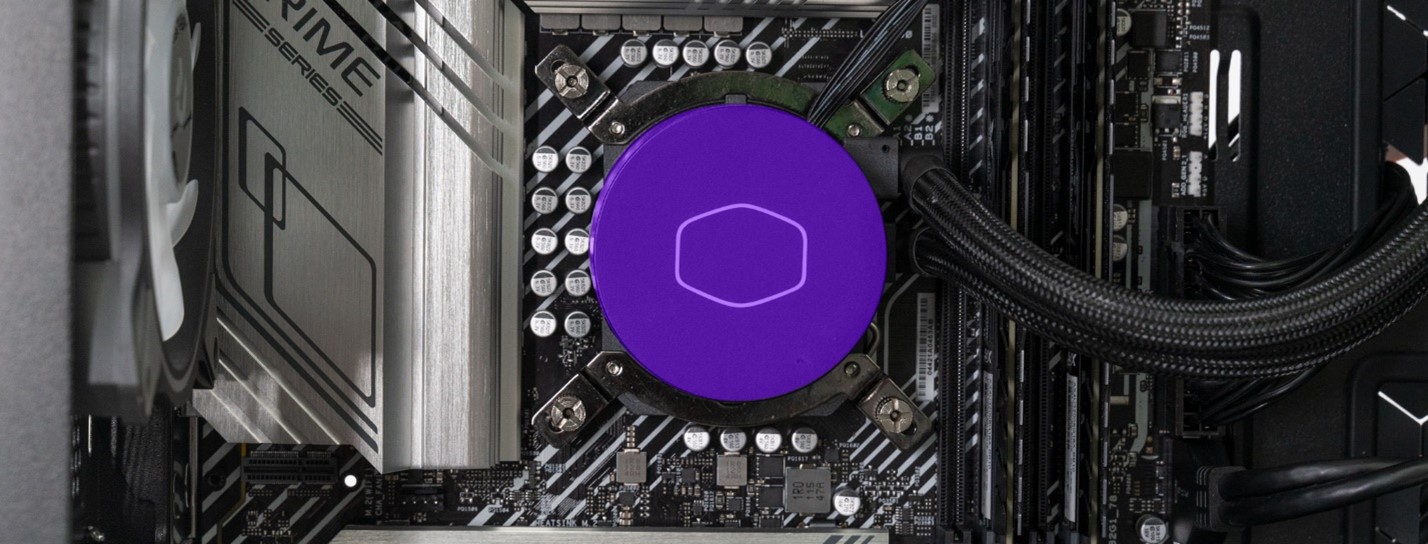
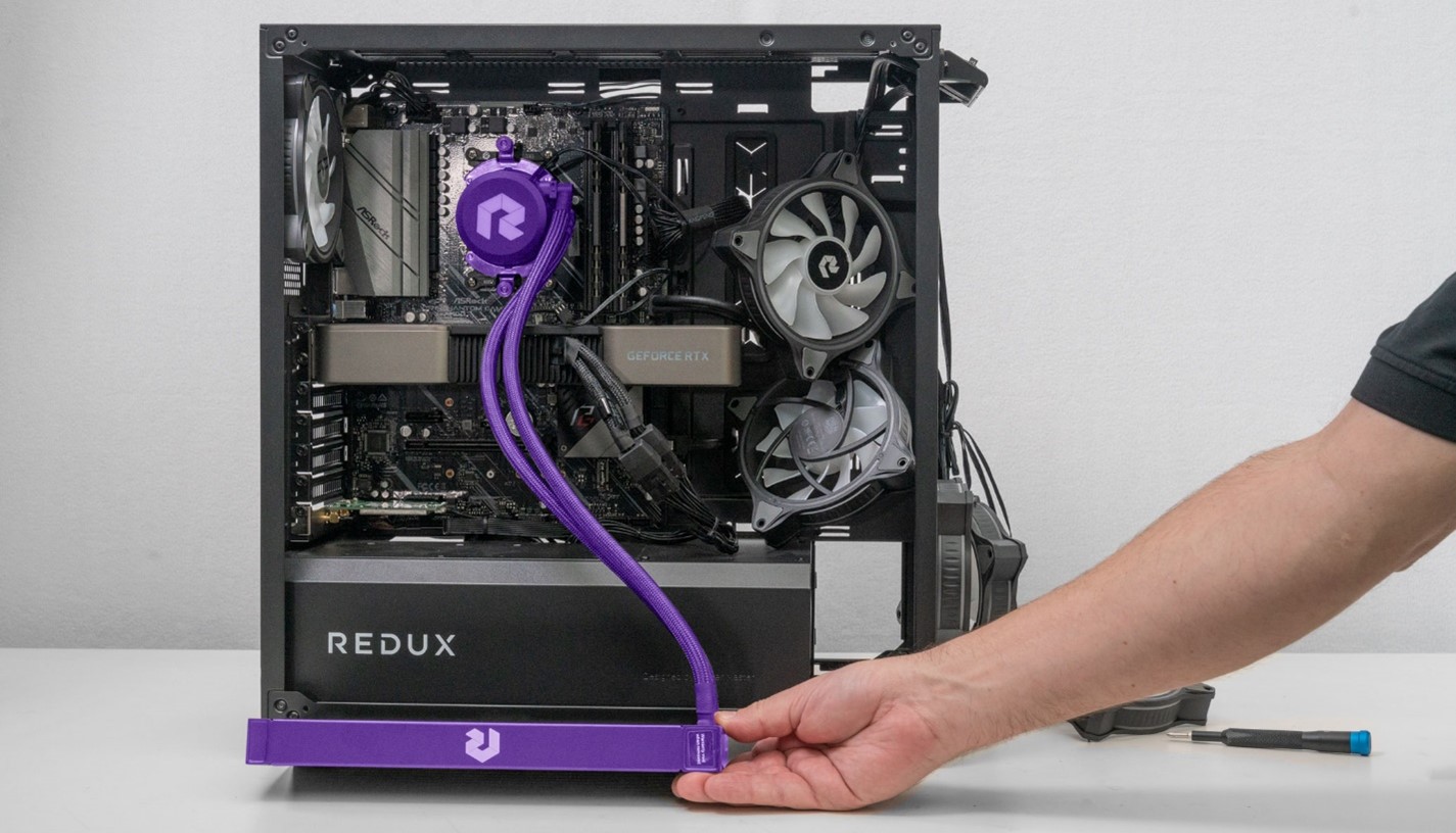
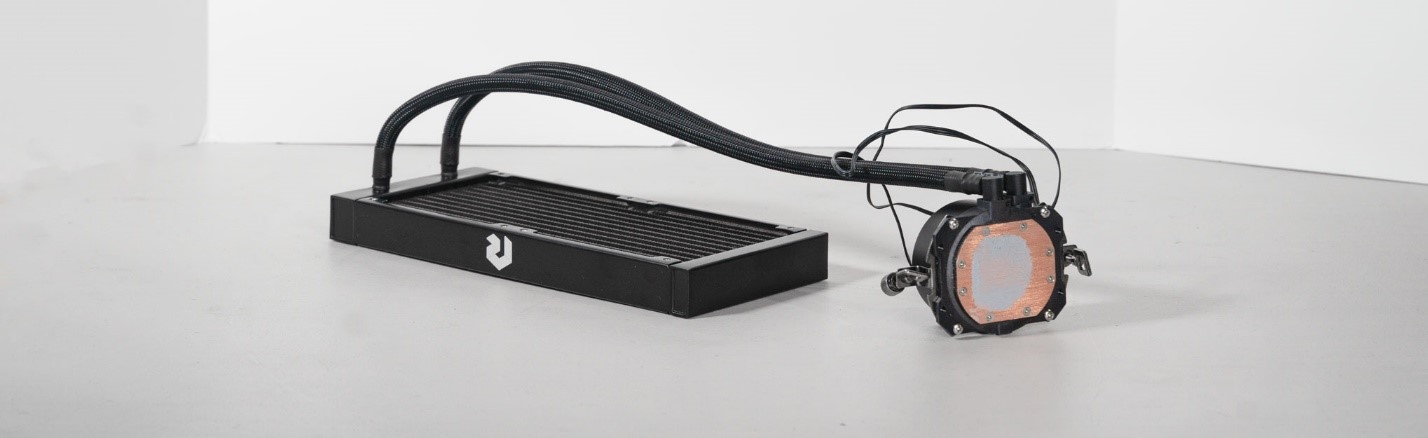
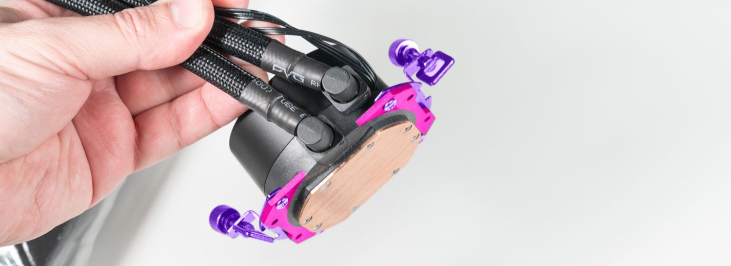
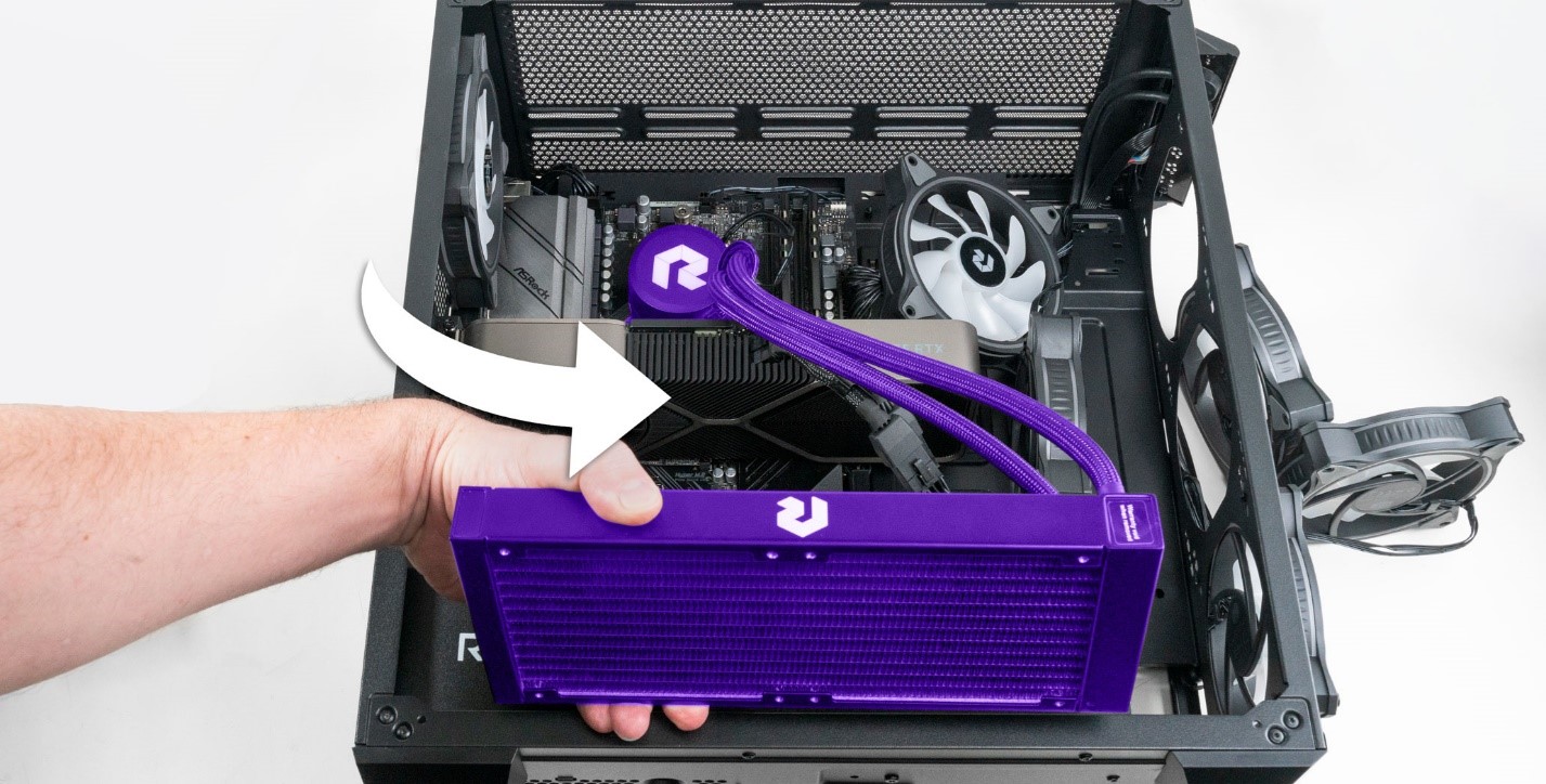
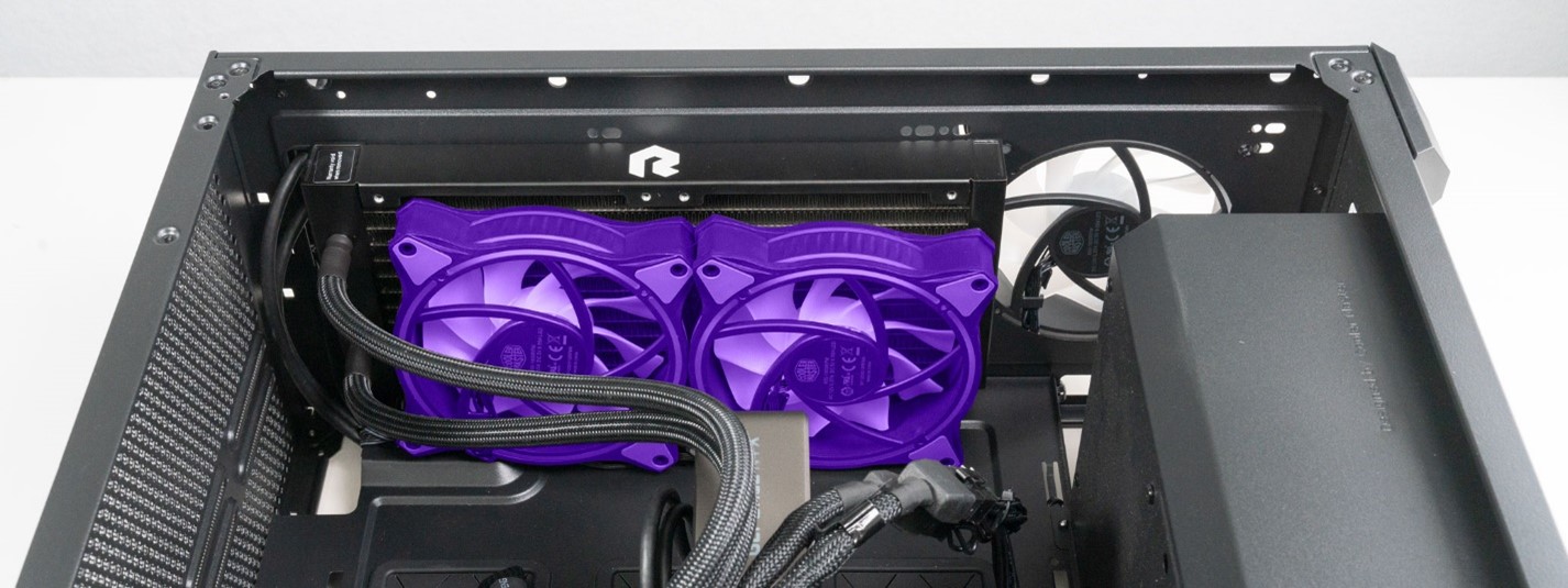
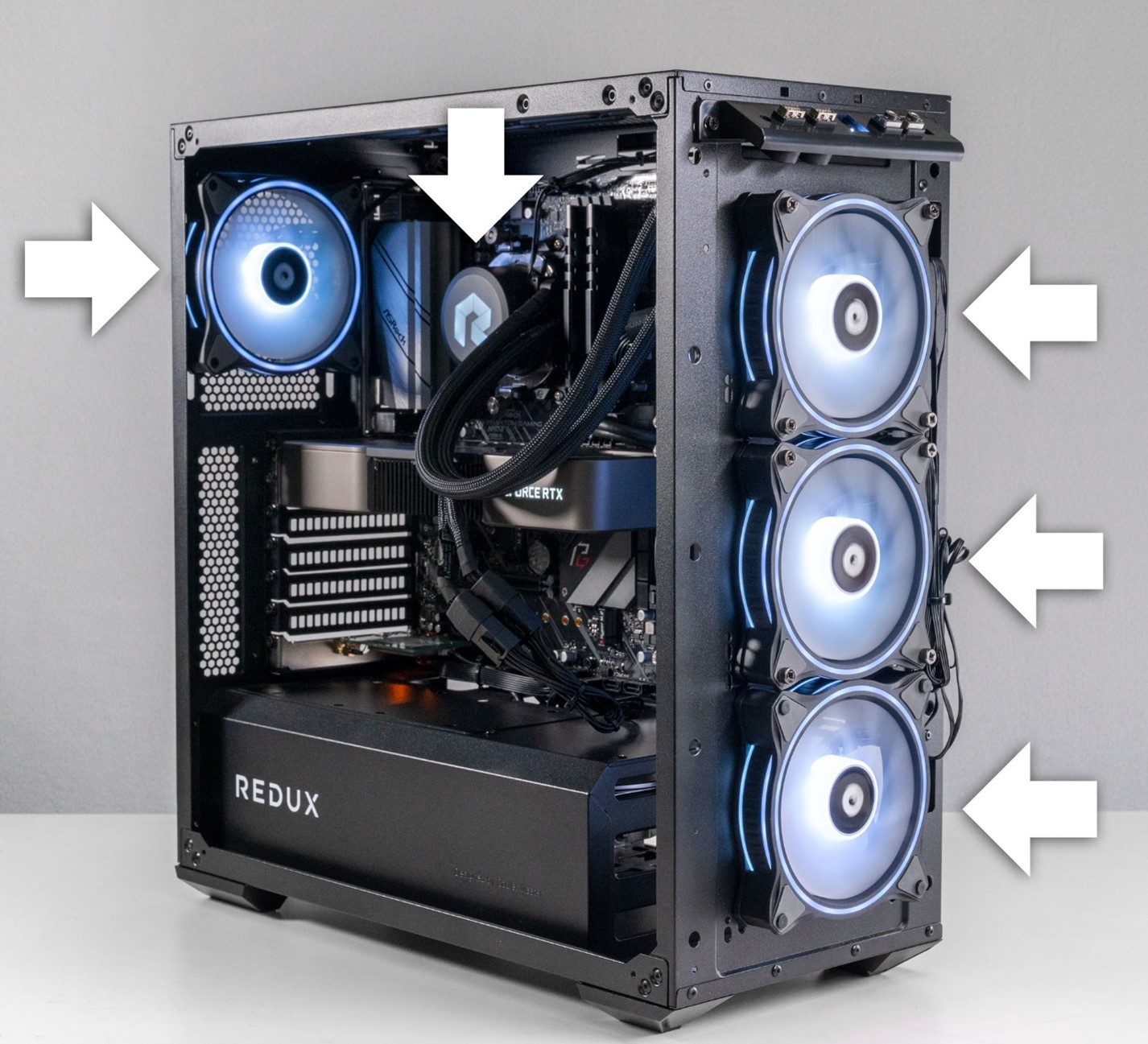
STEP 7: Below is the AIO unit we need to remove. The pump, wires, tubes and radiator are all one unit so will we will need to remove and replace the entire assembly. We will re-use the existing fans.
* CAUTION! *
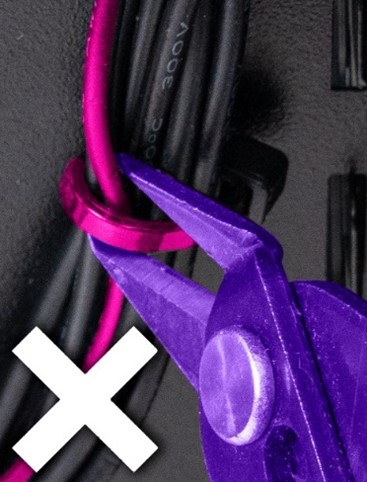
Cut zip ties carefully! Cutting cables will permanently damage them. Damaged components will not be covered under warranty.
 |
 |
 |
|
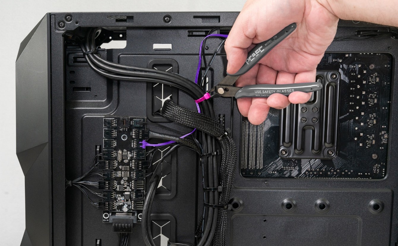
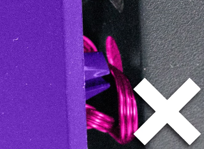
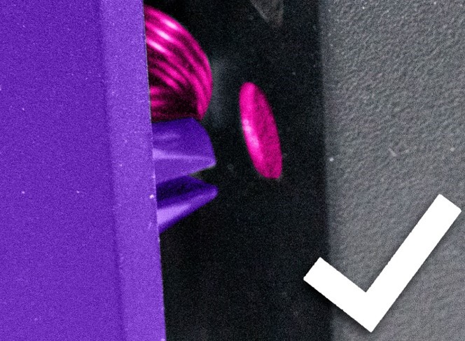
Wire cutter is overlapping zip tie and power cable. Cable will be cut with zip tie. |
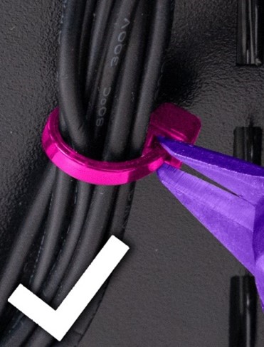
Cut at the zip tie connection end when possible. *Note how we are only using the wire cutter tip, just enough to cut the zip tie and no more. |
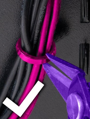
If you can’t reach the zip tie connection end, cut at the gap between two cables. Again, only use enough wire cutter to cut the zip tie. |
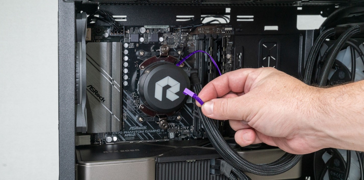
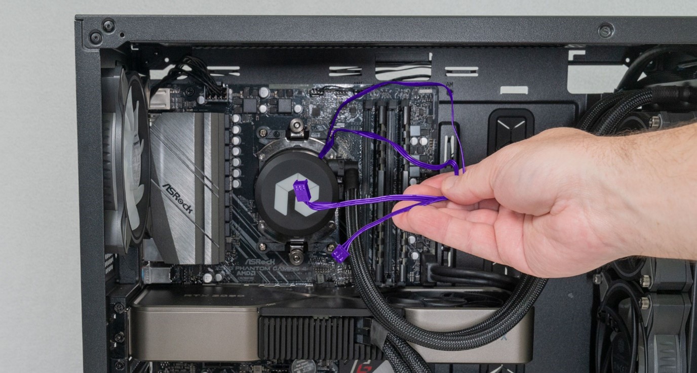
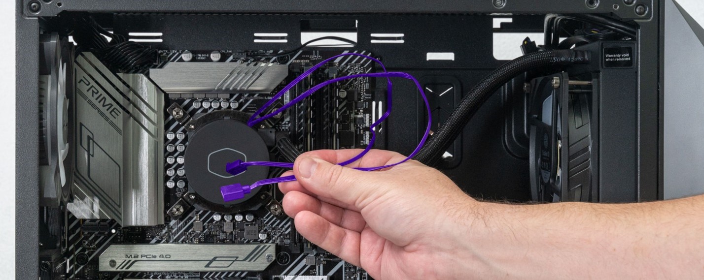
STEP 8: Trace the 2 wires coming out of the pump. We will need to carefully cut any zip ties that run along their length. Our example system has both running to the top right. Your system may differ.

*NOTE* Some systems may have one of the pump cables routed as seen below.

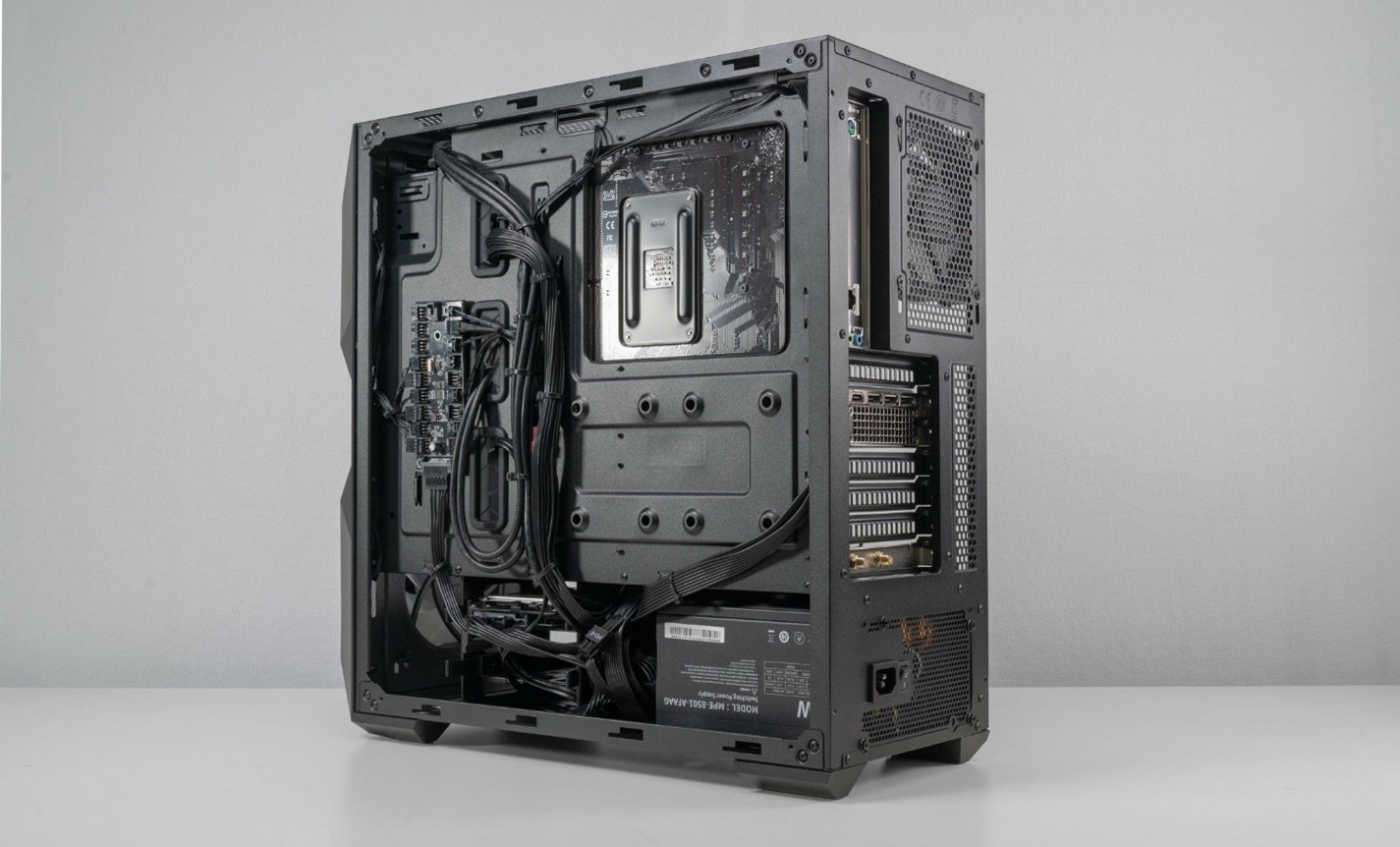
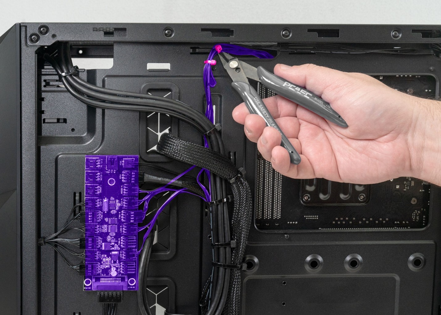
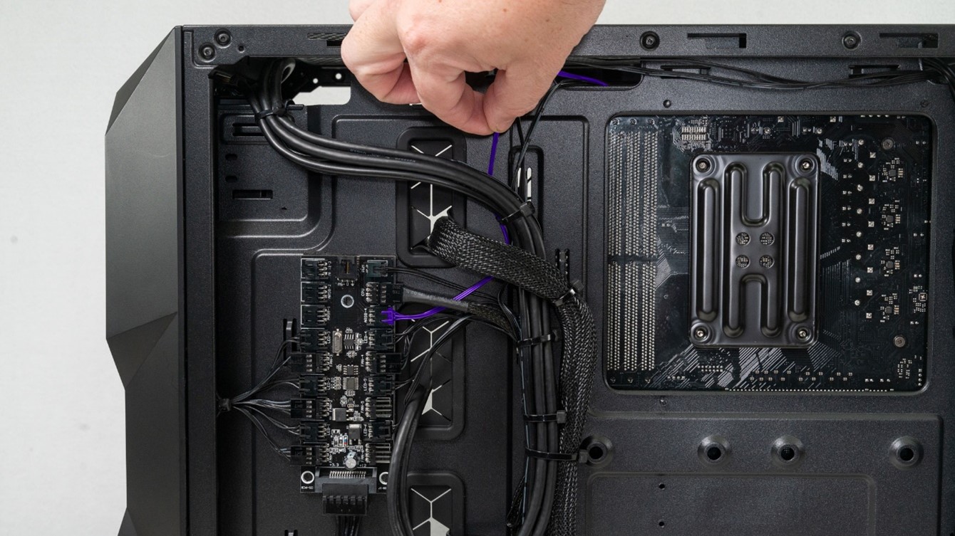
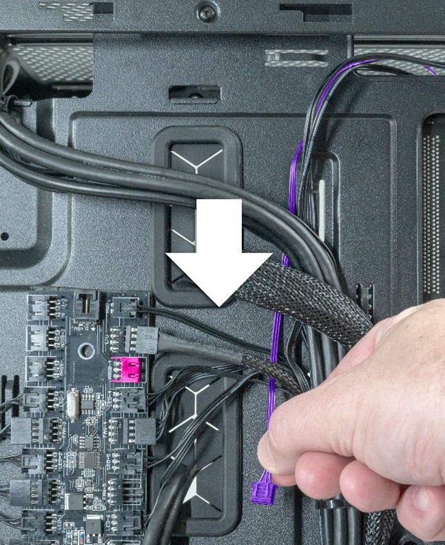
STEP 9: Go to the back side of the system and follow the cables coming out of the pump. Either one or both cables coming from your pump will be wired back here, depending on your system layout.
One cable will go from the pump into the controller board seen below. It’s difficult to trace that cable at first as it is bundled together with other cables.
- Cut the top few zip ties to help loosen the cable, making it easier to trace.
- Do not cut all the zip ties as we are not sure how many we need to cut yet.
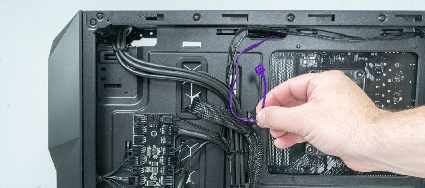
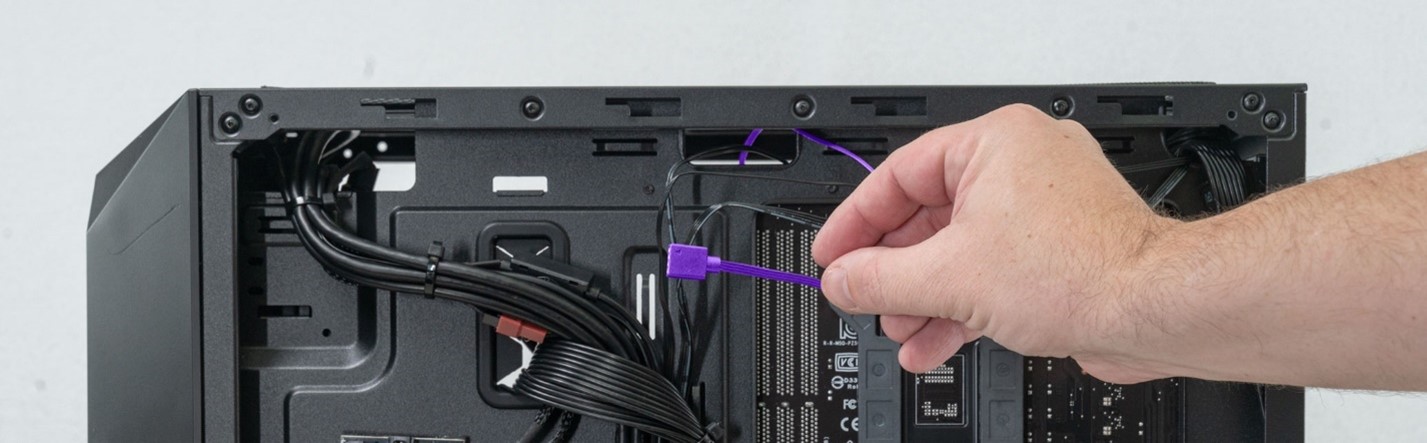
STEP 10: Separate the cables at the top so the cables coming from the pump are easier to isolate.
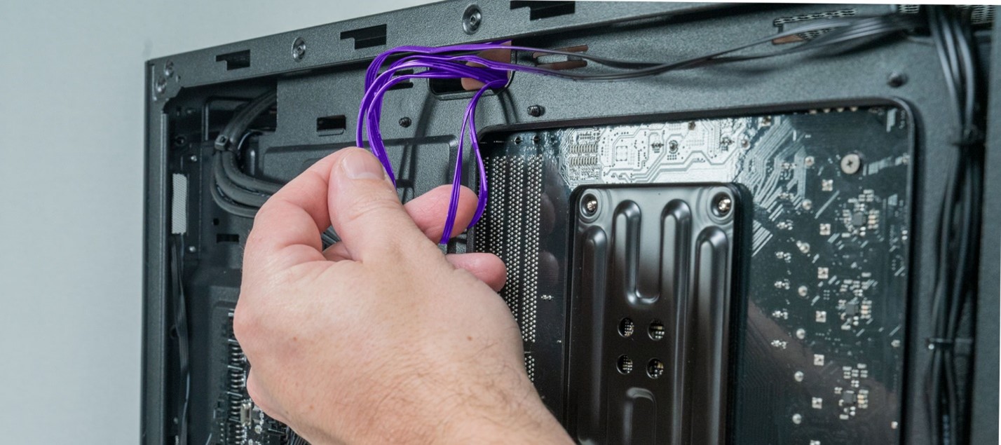
With the cables separated we were able to find and snake our pump power cable through to the mainboard side. This is one of 2 cables we need to disconnect and bring through to the mainboard side of the case. *Note* as stated previously some systems will have this cable run differently.
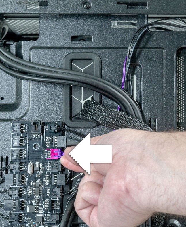
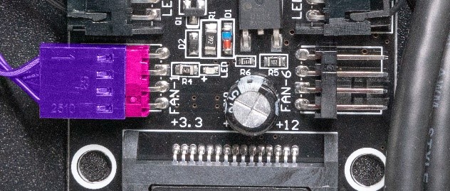
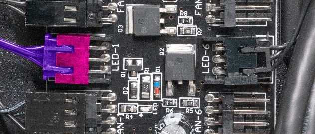
STEP 11: Trace the other wire coming from the pump. Our remaining wire goes to the LED/ FAN controller as shown below.
STEP 12: Carefully cut any zip ties holding the pump cable to the case.
STEP 13: Unplug the cable by gently pulling it out of the LED/ FAN controller.

Snake the cable out from the other cables.
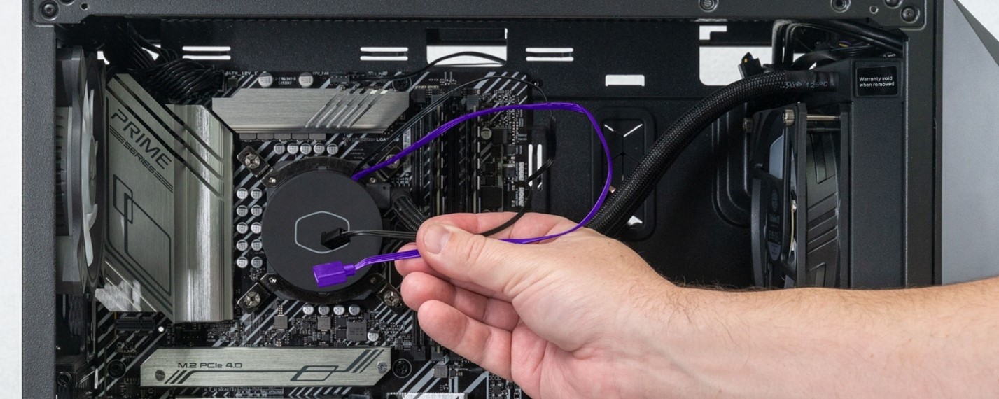
STEP 14: Pull the cable through to the mainboard side of the system. We can let these cables hang freely for now.
*NOTE* Some systems may be configured with a similar but slightly differently styled pump.
If your pump top looks like the one below, the LED cable will be wired differently.
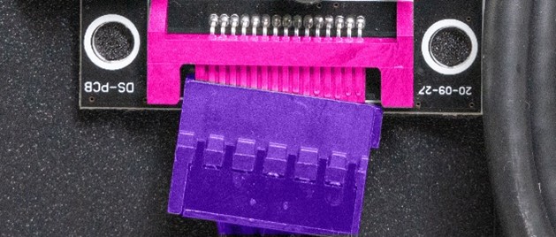
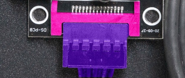
Instead of the LED cable running directly to the control board, this pump has an LED cable running to a small splitter box as seen below. *NOTE There may be multiple splitter boxes, we only need to worry about the one the pump cable goes to. Trace the pump cable to the correct location.

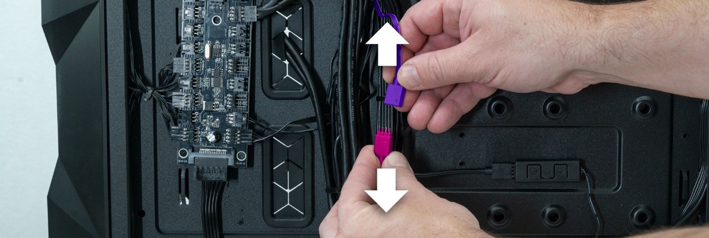
Once you find the box, Pull the cover off, this reveals two connectors.
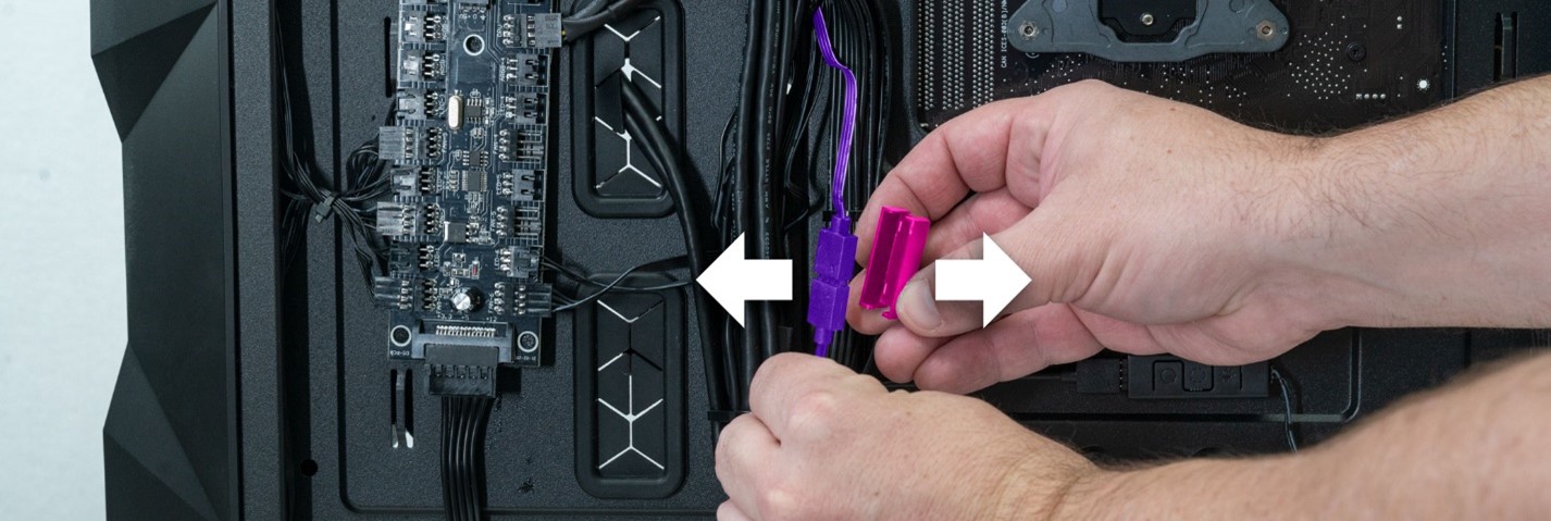
Gently pull the two pieces apart.
Pull the LED cable through to the front side. Make sure it and the pump cable are fully unplugged from the PC as seen below.
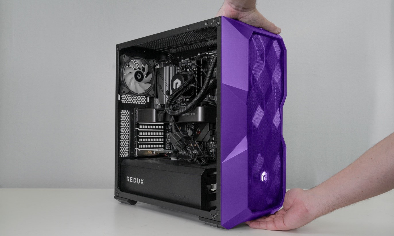
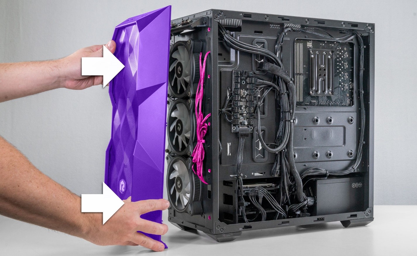
STEP 15: Next, we need to pull off the front panel to access the radiator fan screws. Place one hand gently on the top edge of the front panel and hook your other hand under the bottom front panel lip.
*NOTE* unplug all cables/ devices from the top front of the PC before removing the front panel.
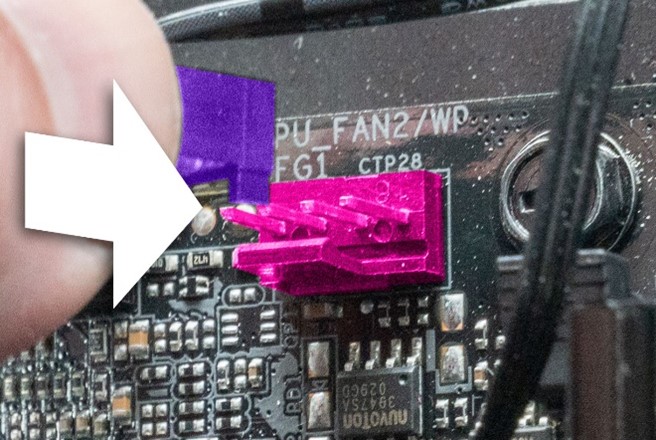
In the below example photo, you can see the indented lip on the front panel’s bottom. Hook your fingers in here.

STEP 16: Keep your hand gently resting on the top of the front panel (this helps to stabilize the panel when you pull it off.)
Use your lower hand to pull the bottom of the case, out, away from the computer. This requires a bit of force. If it doesn’t come off the first time, try again, adding a little more force each time until the panel pops off.
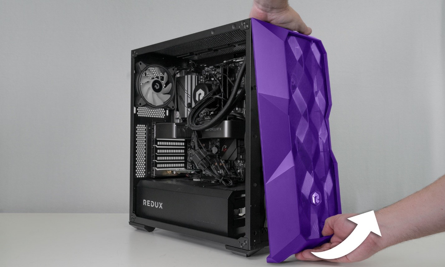
STEP 17: The whole front panel will pop off. Gently set it to off to the side for now.
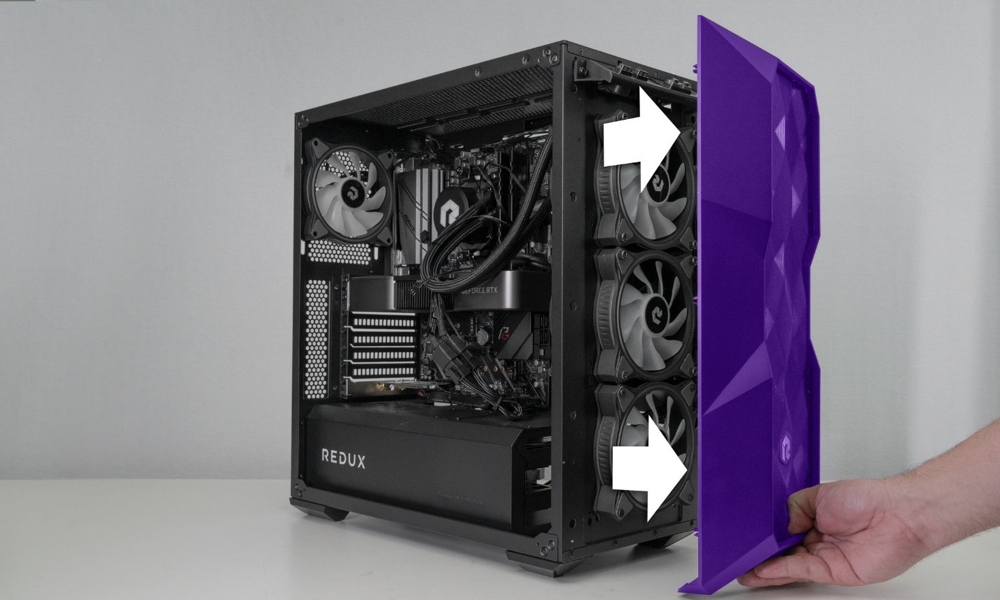
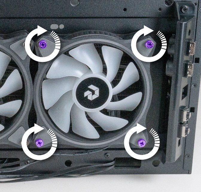
STEP 18: Now we need to remove the 2 fans that connect to the back of the radiator. Start with the bottom fan and use a Phillips head screwdriver to loosen and remove the 4 screws.
If a screwdriver won’t fit or reach the rear screws, you can use a pair of pliers to loosen them.
STEP 19: Remove all 4 screws from the bottom fan and let it gently hang by its wires. Don’t worry, the cables won’t be harmed by the fan hanging.
- Once the bottom fan is unscrewed, remove the 4 screws from the top fan.
We now have both fans unscrewed and hanging by their wires.
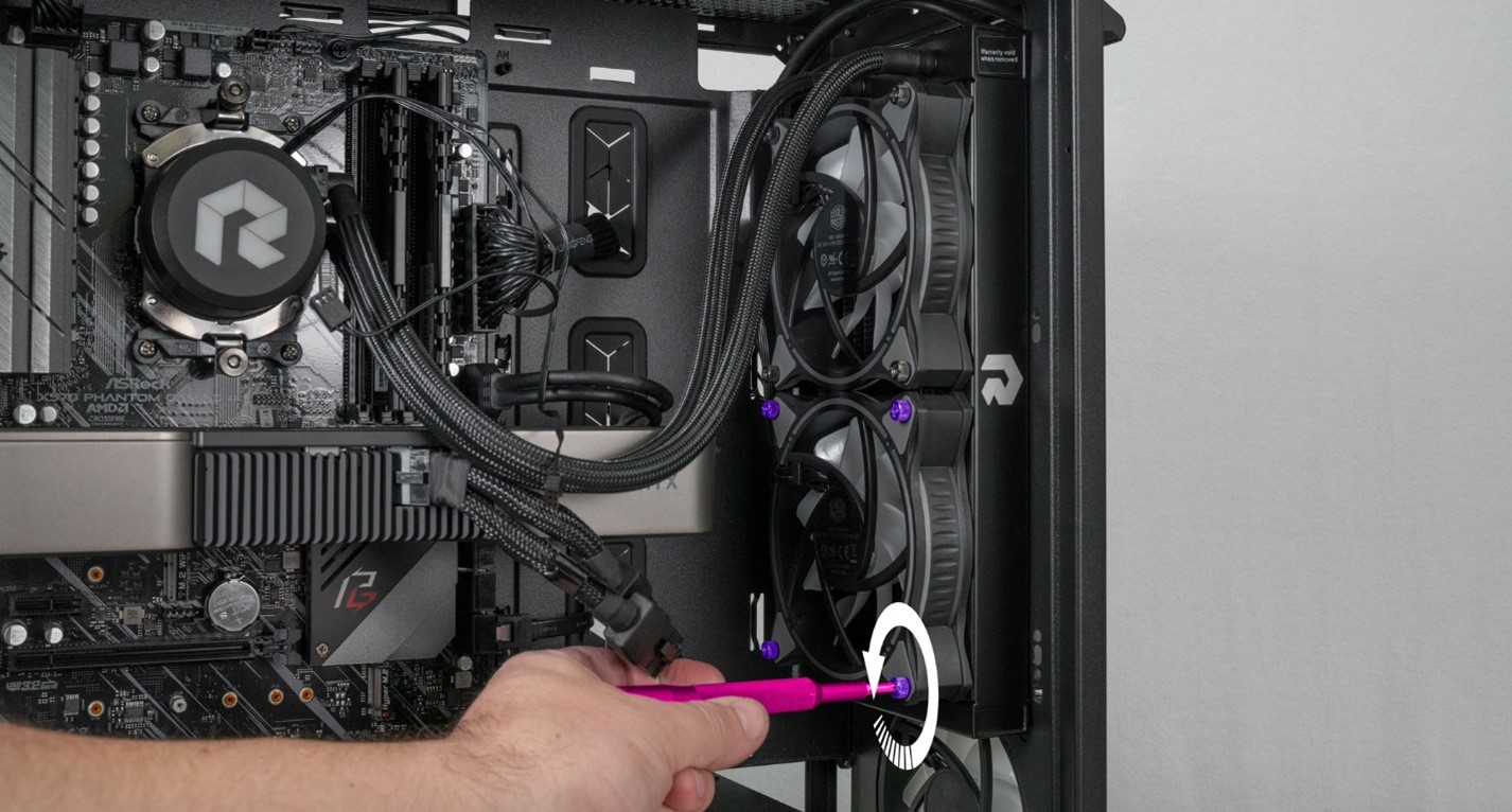
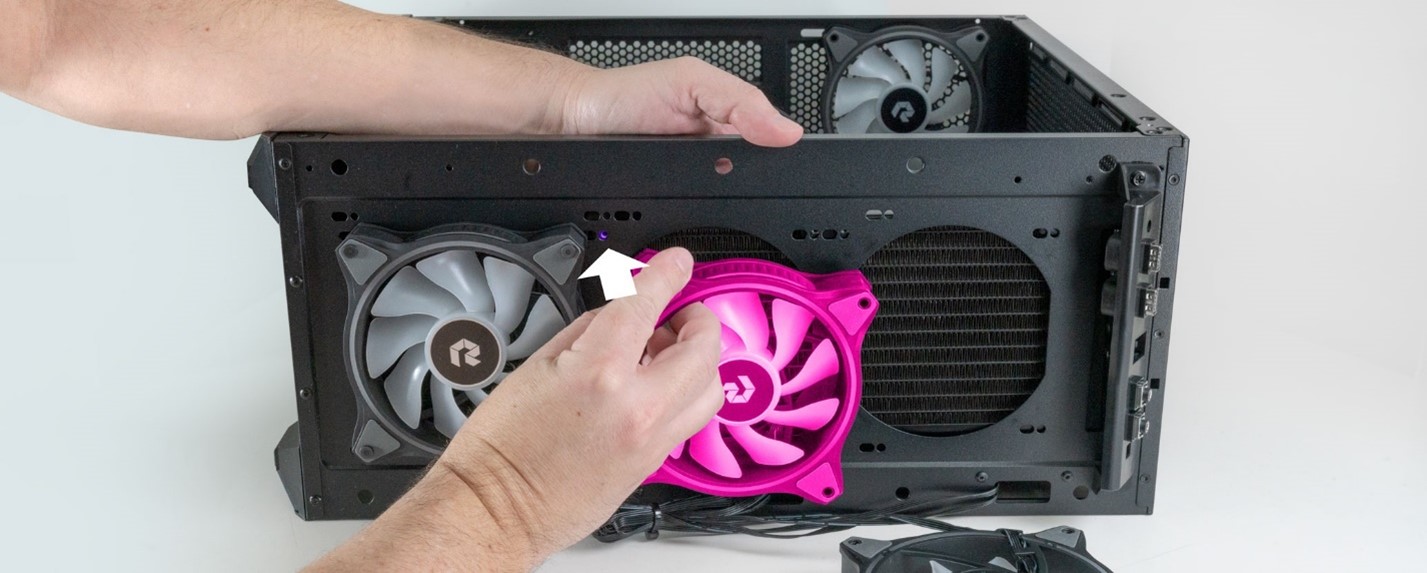
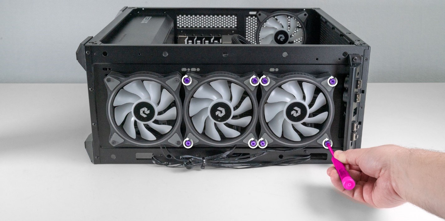
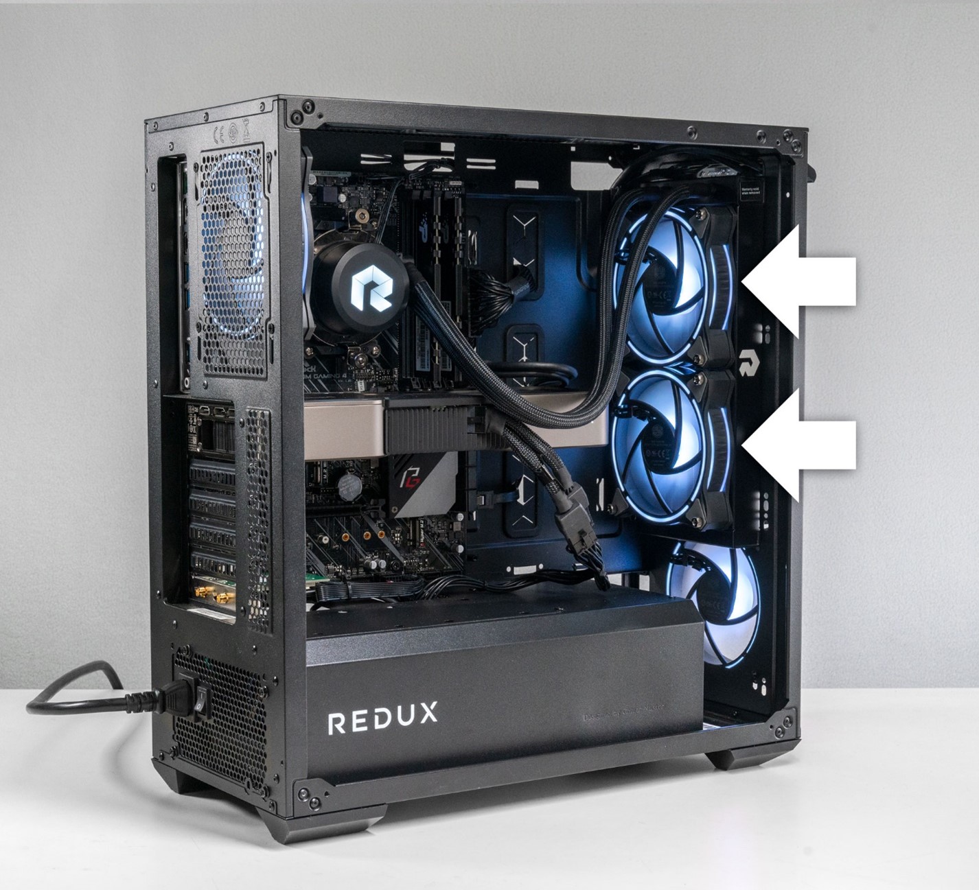
STEP 20: Go to the front of the case. We need to remove the screws from the fans connected to the radiator. In our example build this would be the middle and top fan. Other builds may have a longer 3 fan radiators. In those builds, all 3 fans will need to be removed.
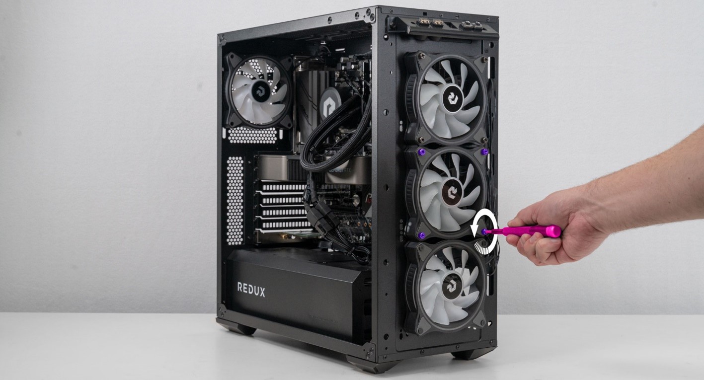
STEP 21: Remove the bottom fan and let it gently hang. It’s best to do this proactively so it does not fall off later.
- Move on to the top fan but only remove 3 of the 4 screws.
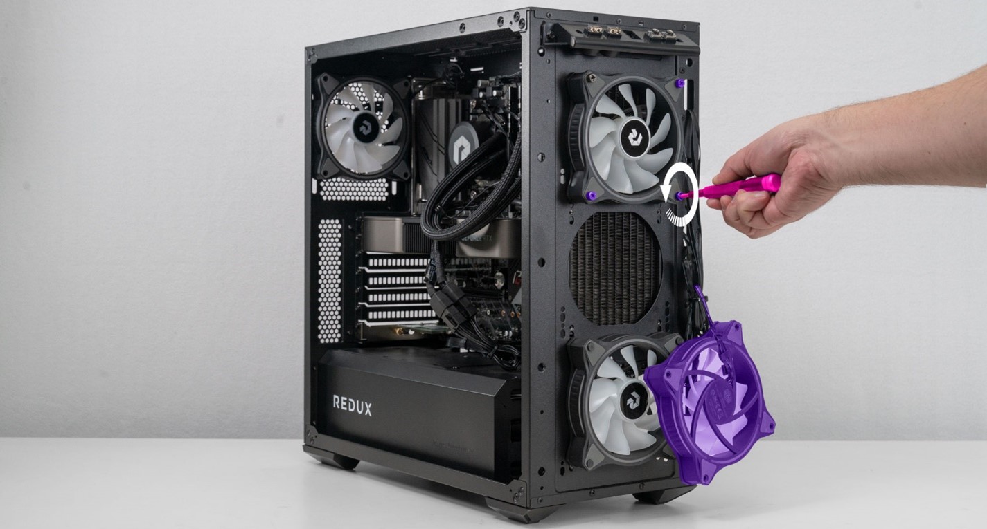
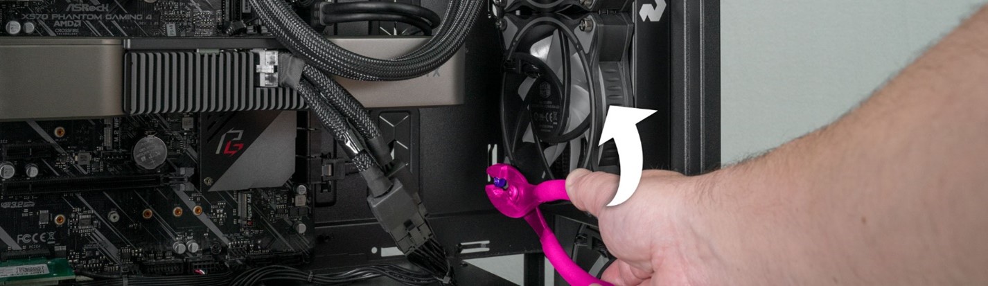
The last screw is all that’s holding the radiator to the case. Reach a hand inside the case and gently hold the radiator in place before removing the last screw. With the radiator secured, remove the last screw.
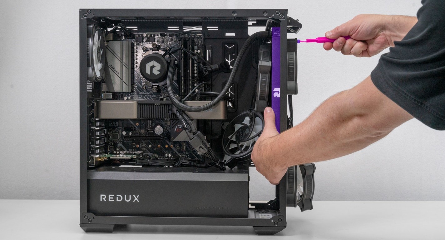
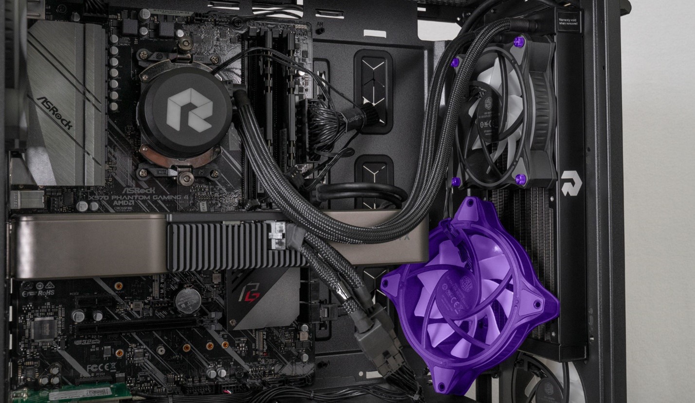
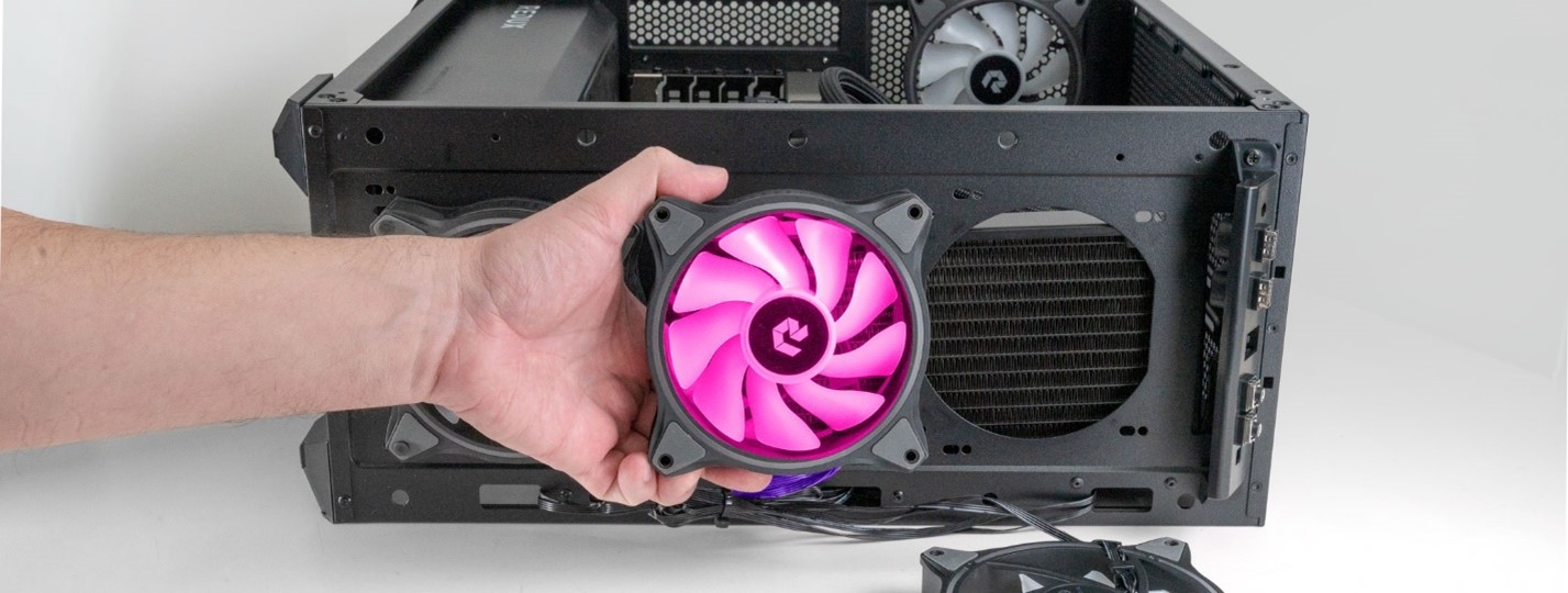
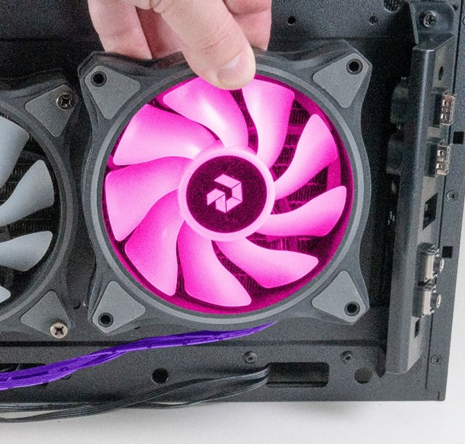
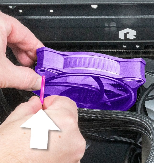
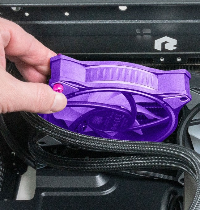
STEP 22: While holding the radiator, gently remove the top front fan.
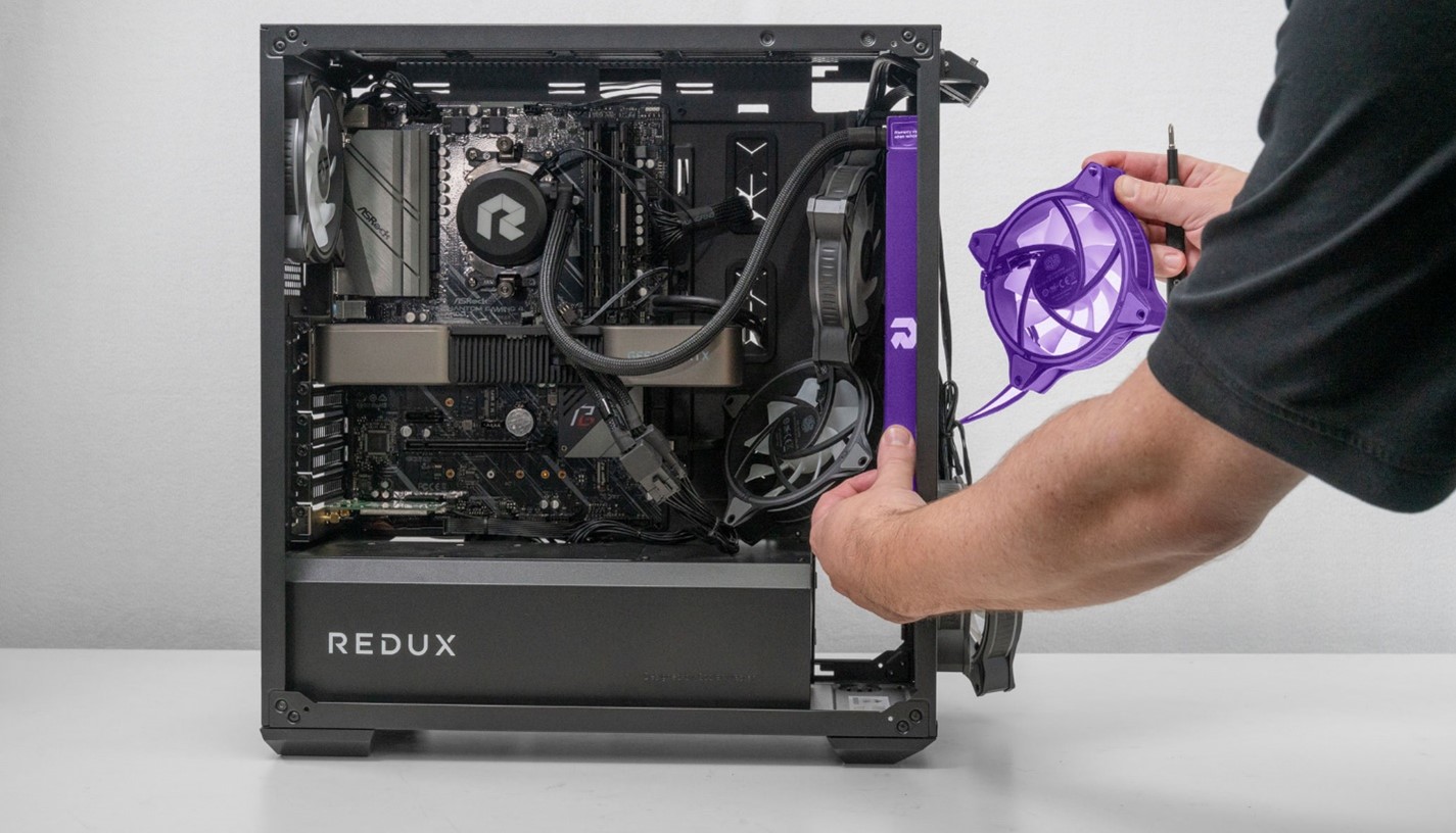
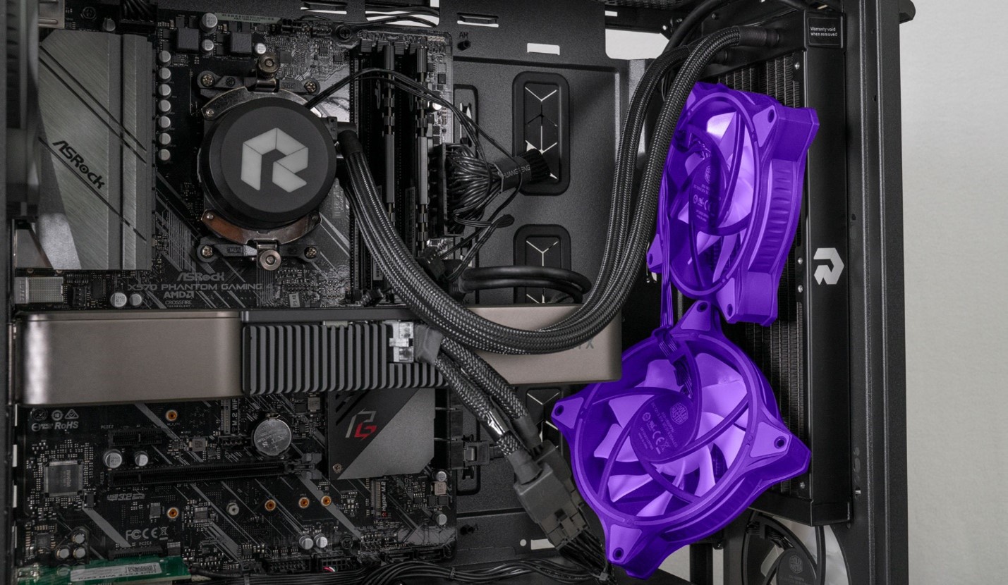
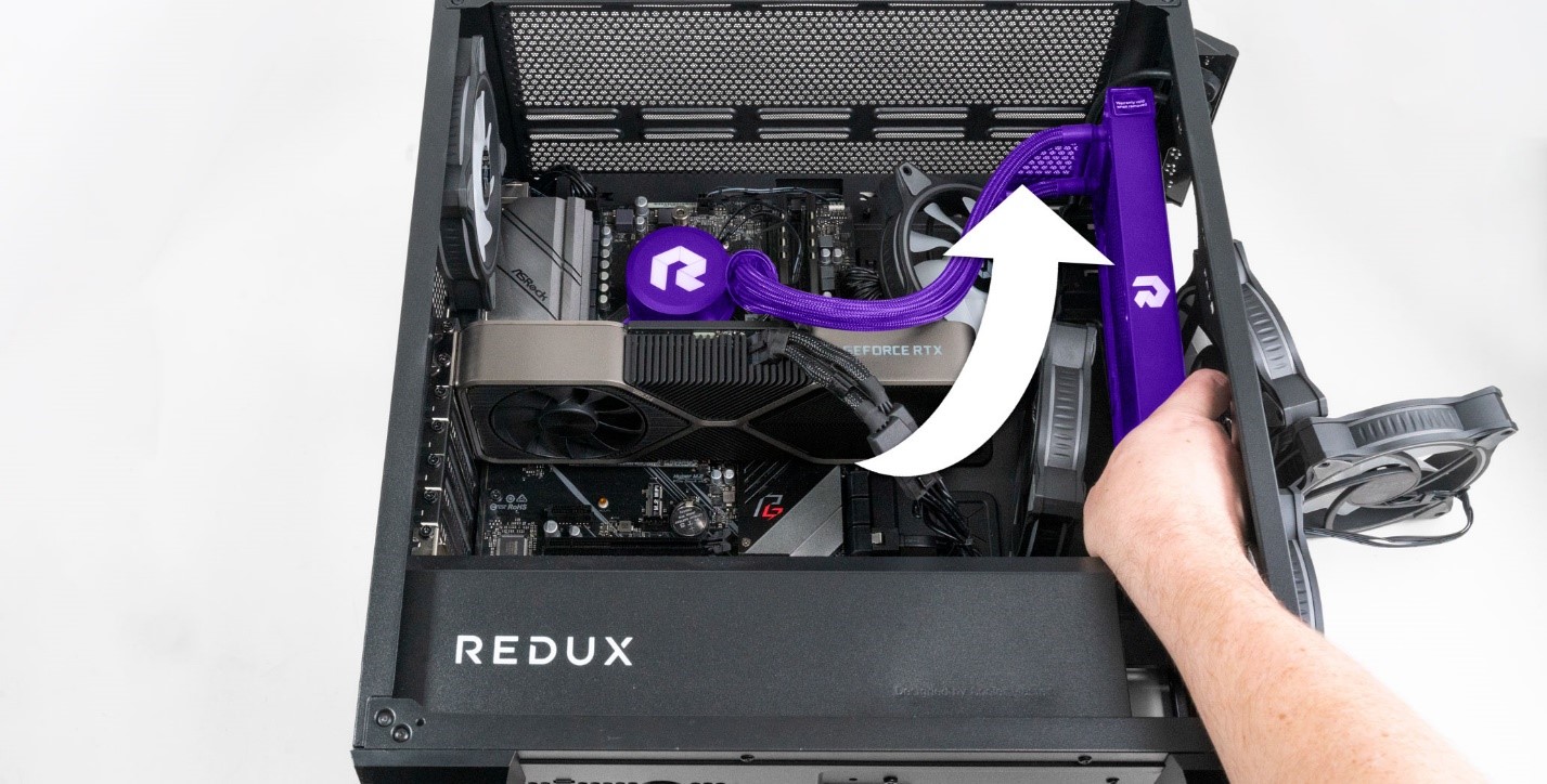
Gently set the fan aside and grab the radiator with both hands. Gently maneuver it out of the case.
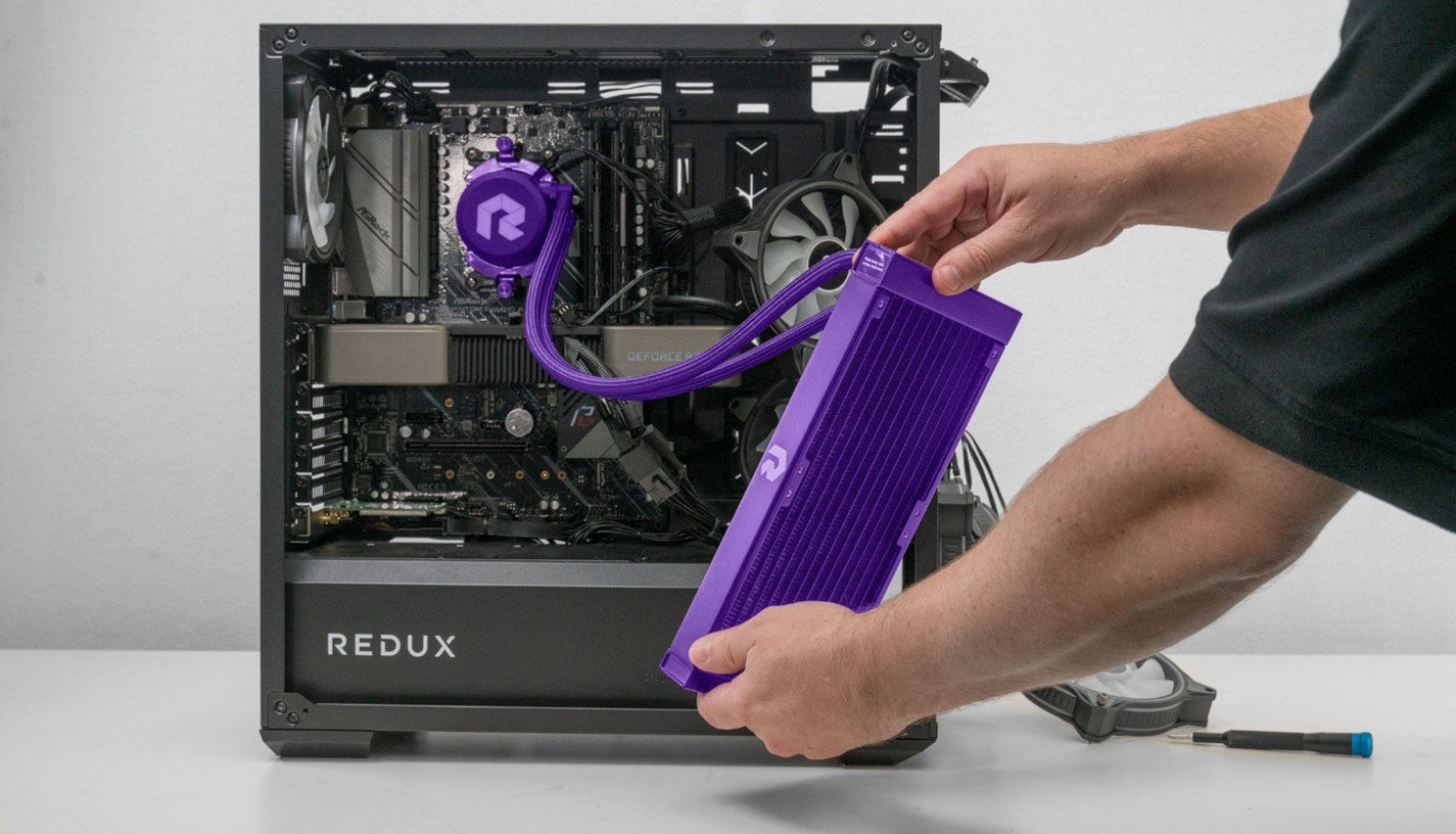
Carefully set the radiator down on the desk. It’s okay if the radiator hangs slightly by the tubes but do your best to not put undue stress on the tubes.
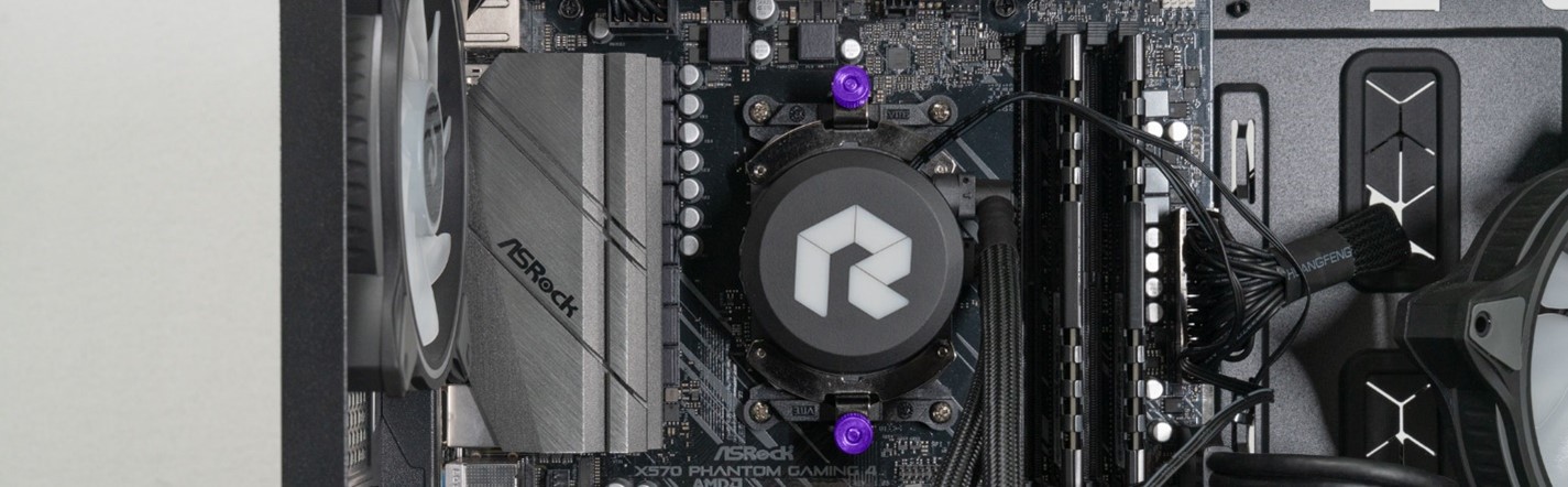
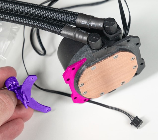
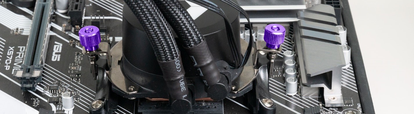
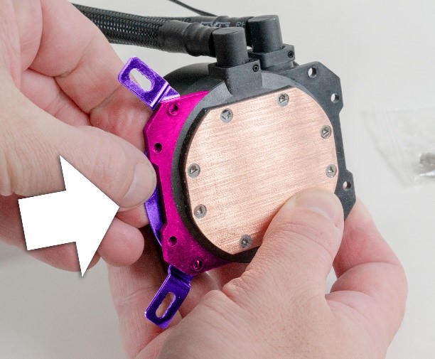
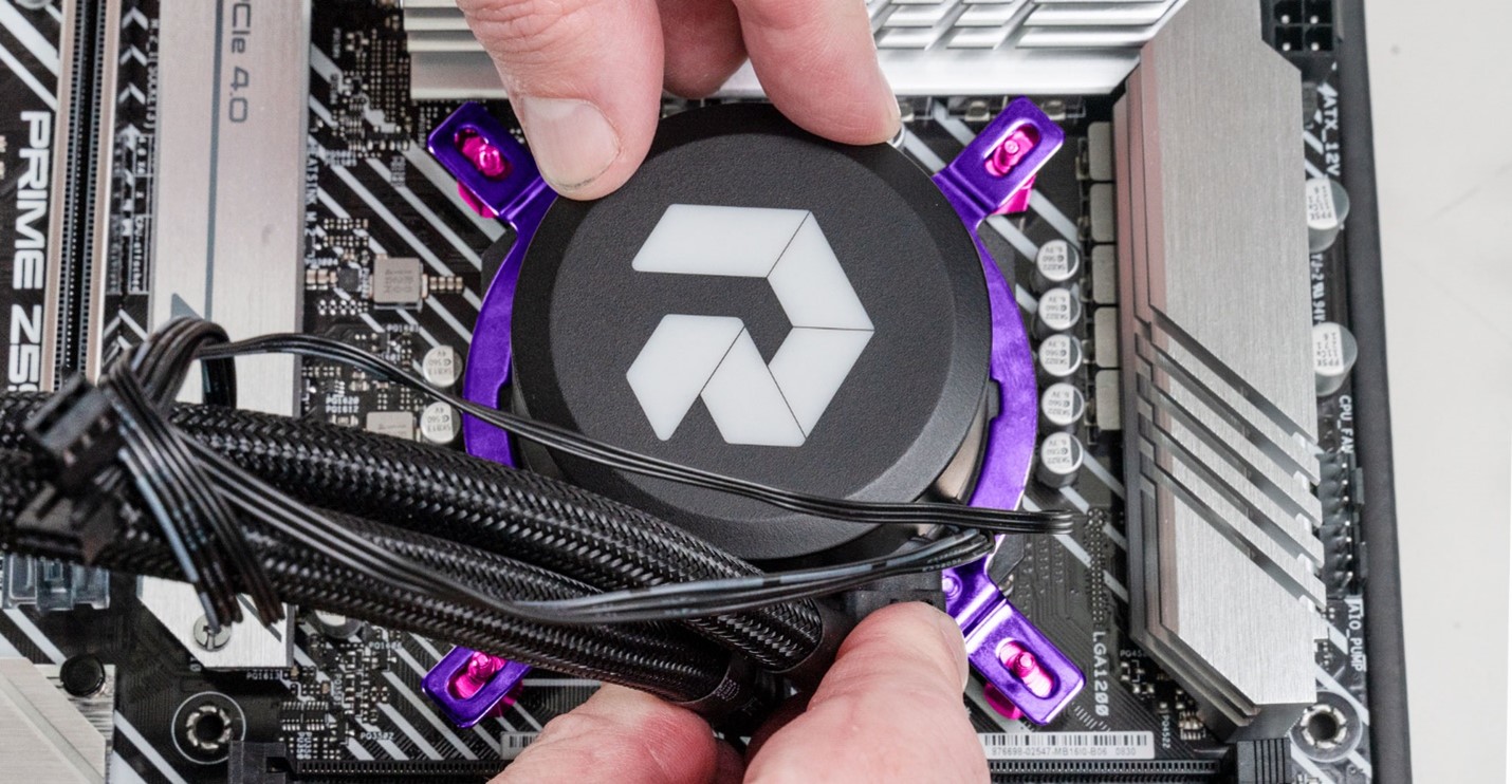
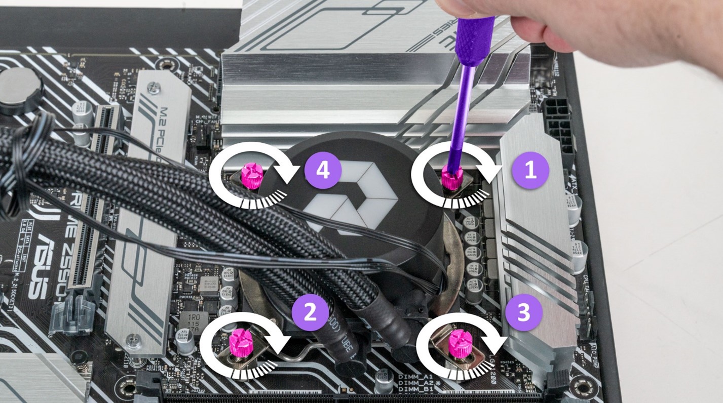
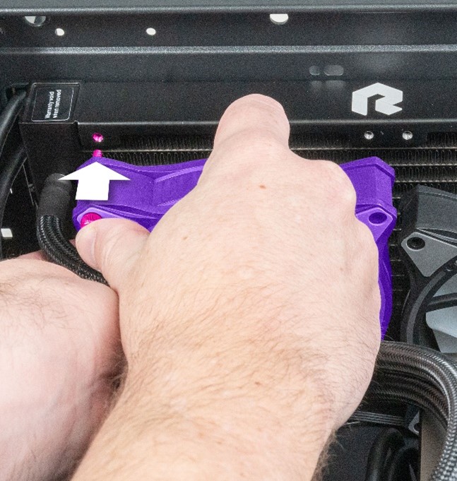
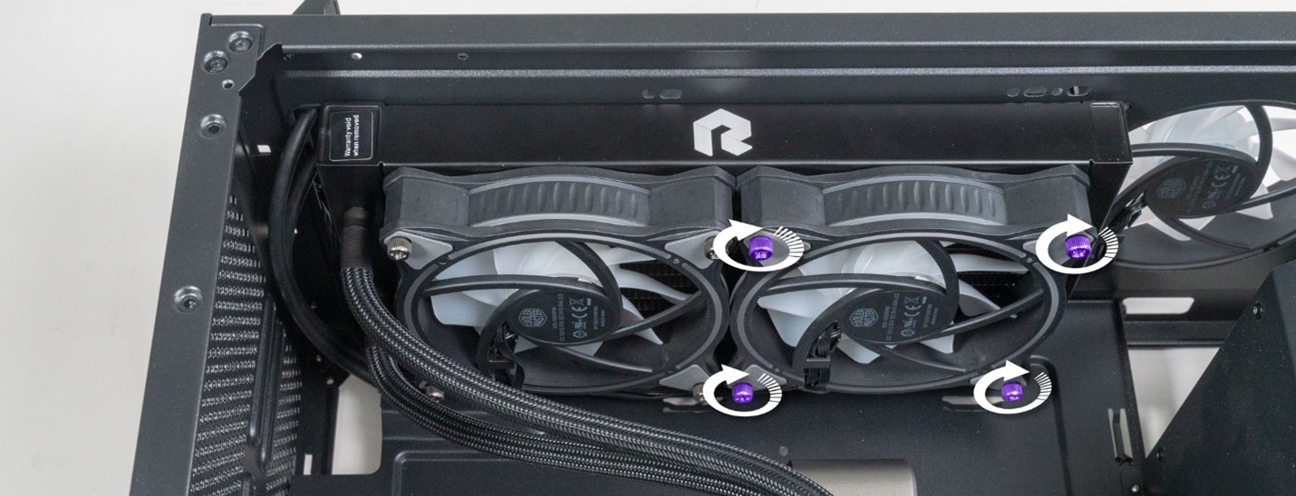
STEP 23: Next, we need to remove the screws holding the pump body to the mainboard. The style of screws will differ for AMD and intel systems.
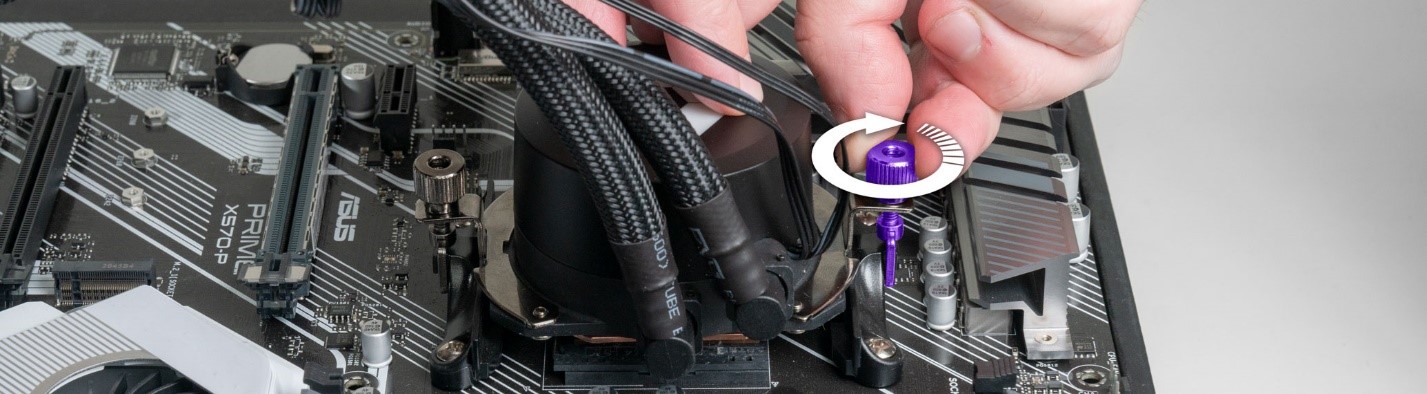
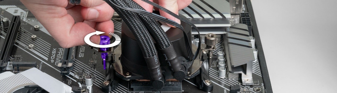
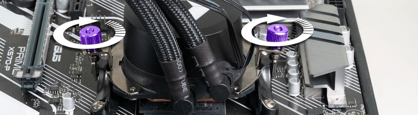
On AMD systems, there will be 2x large thumb screws that need to be undone. We will go over AMD brackets first and Intel brackets second.
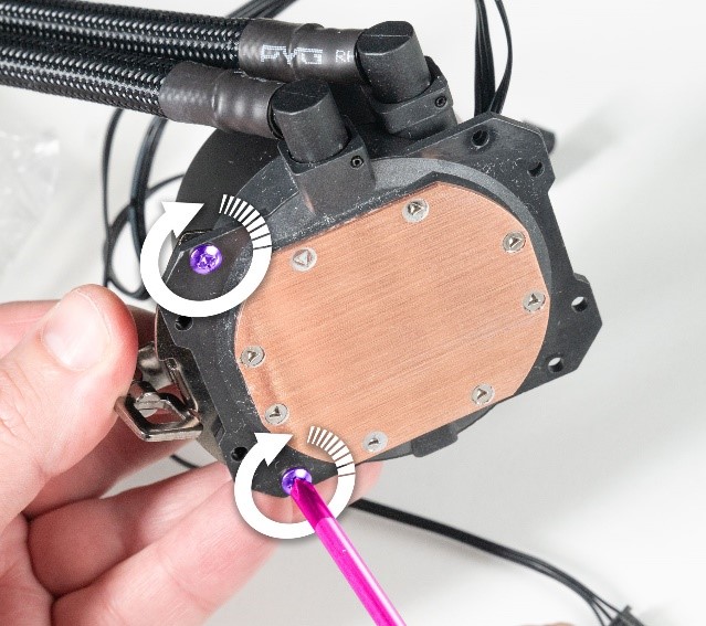
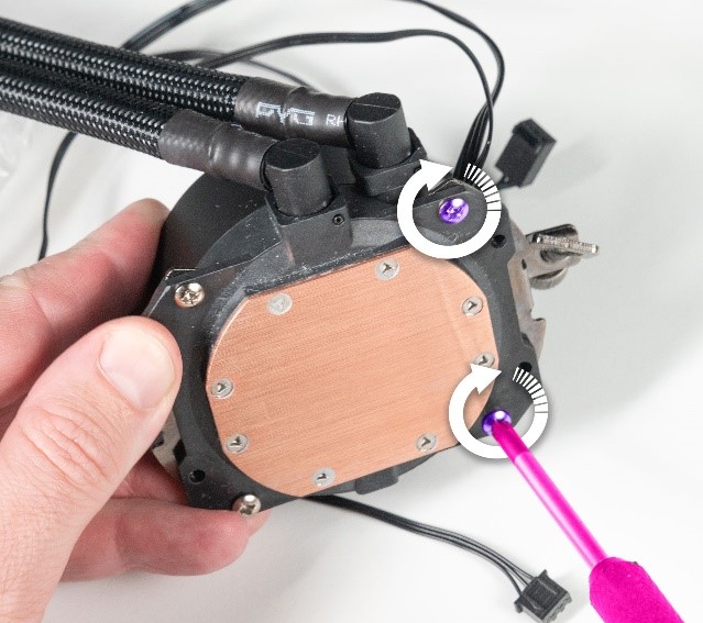
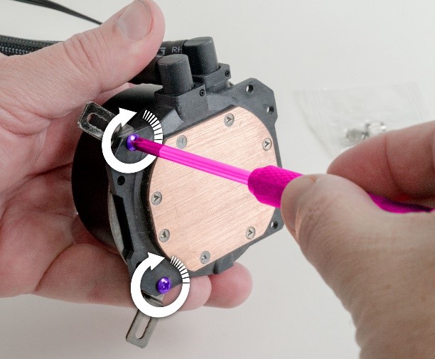
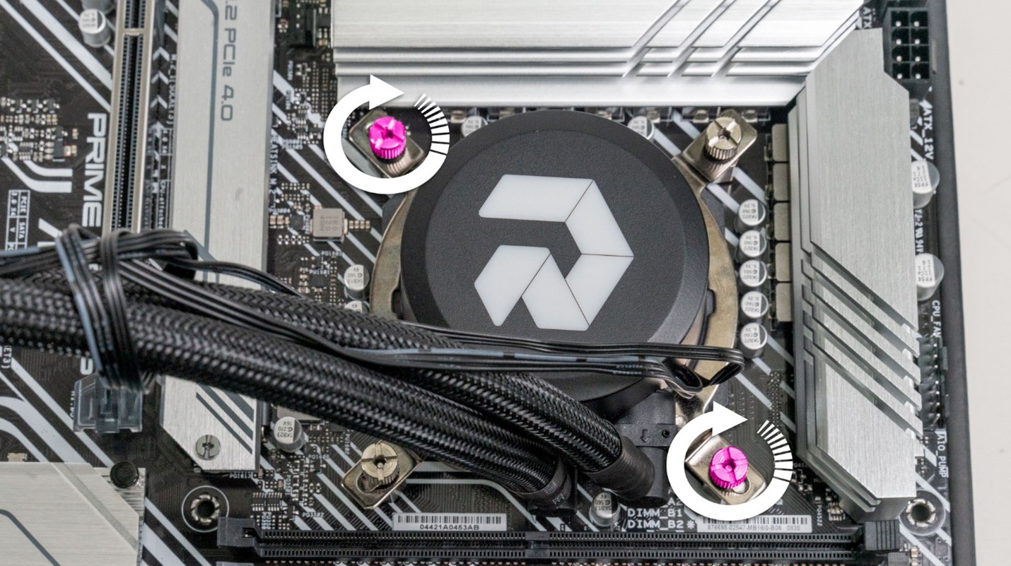
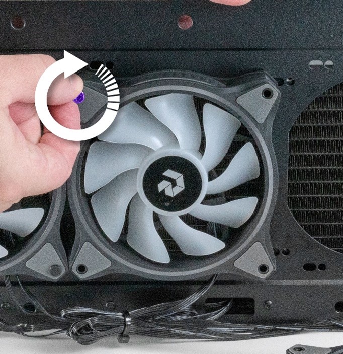
We need to untighten each screw a little at a time until both screws are fully untightened. This will help to release pressure evenly, preventing damage to the CPU and mainboard.
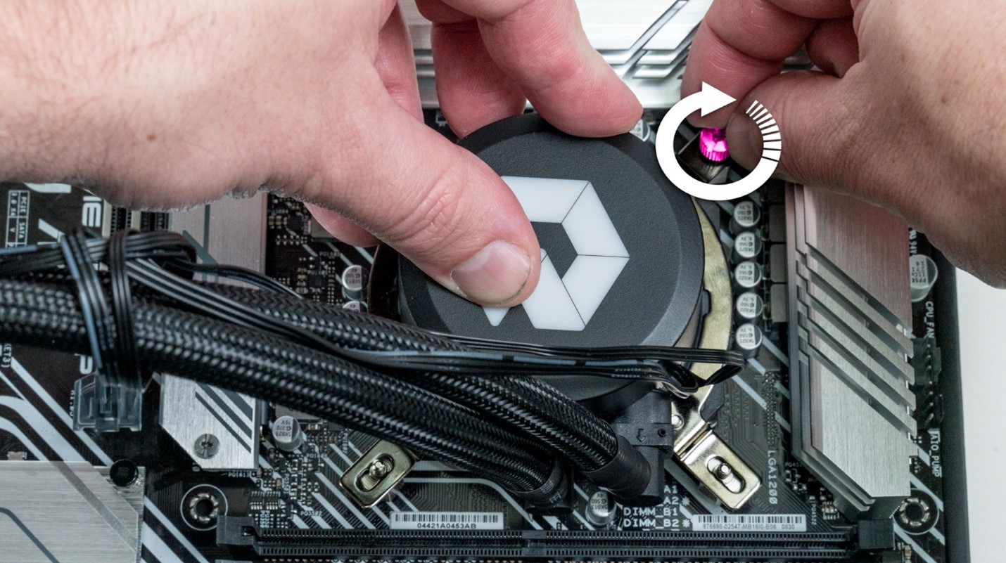
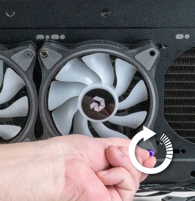
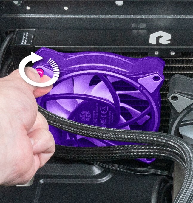
Grab the top screw and rotate it counterclockwise half a turn.
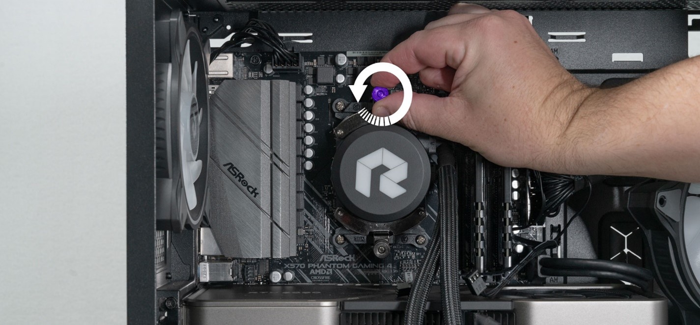
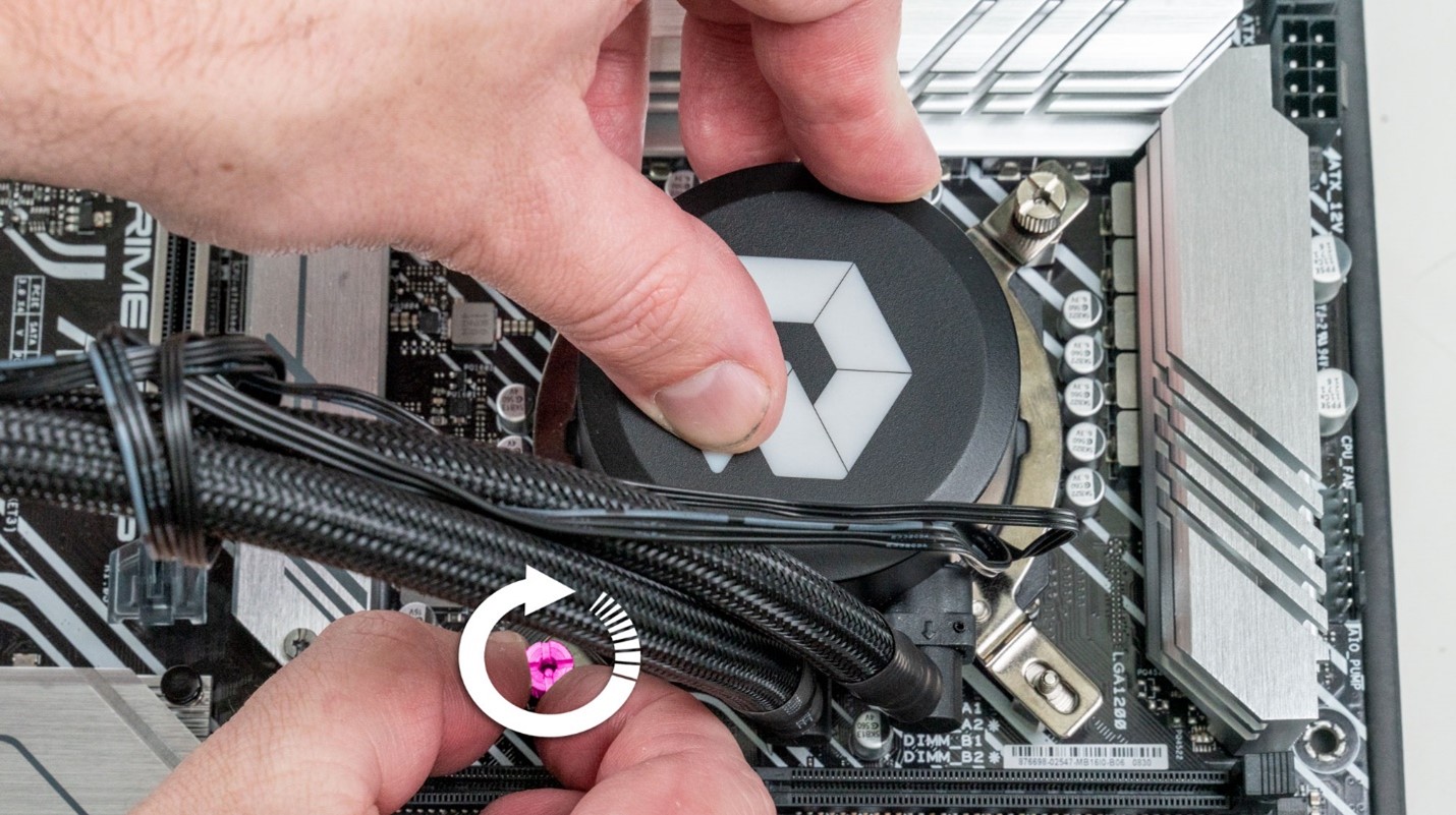
Next go to the bottom screw and rotate it half a turn.
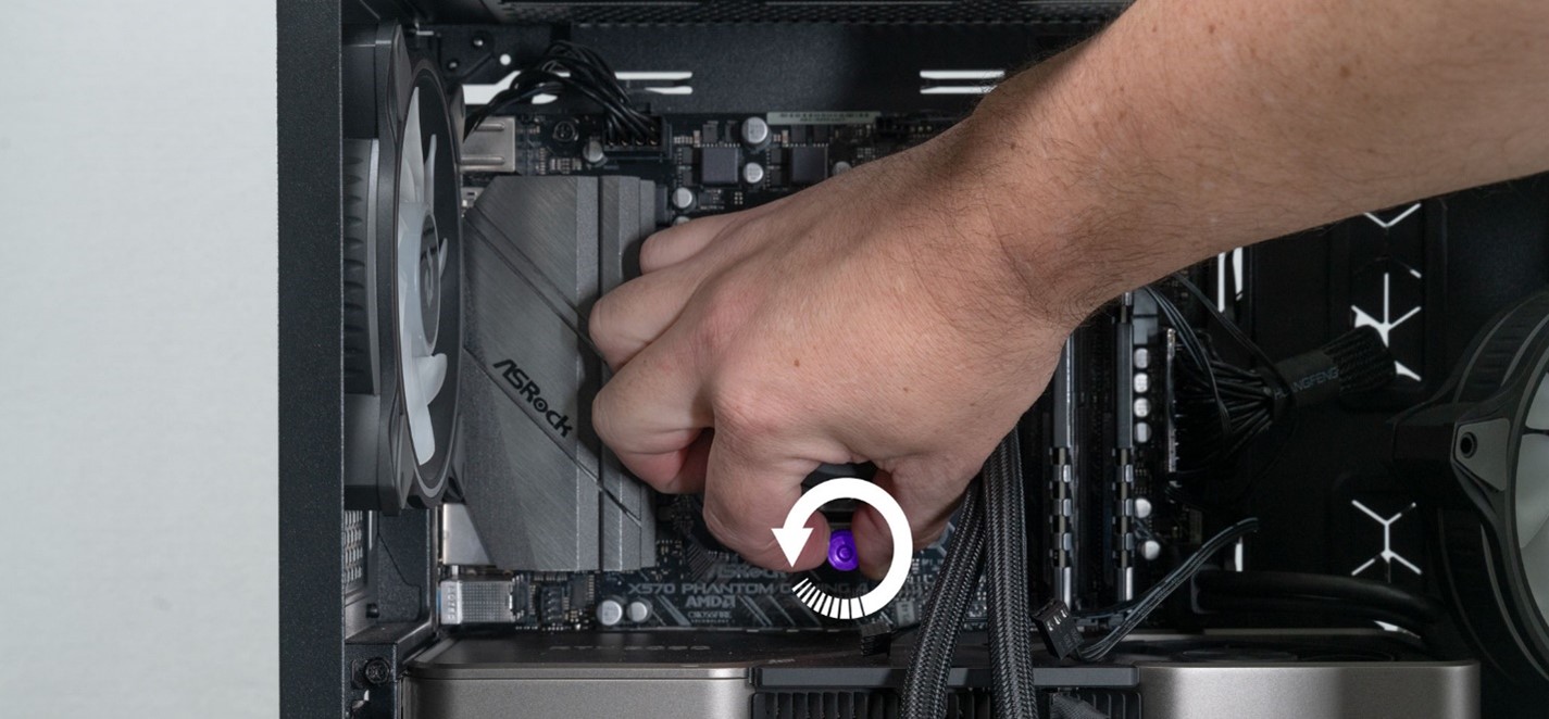
Repeat this process until both screws are fully unscrewed.
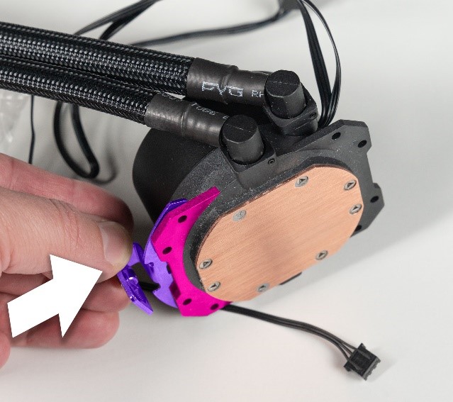
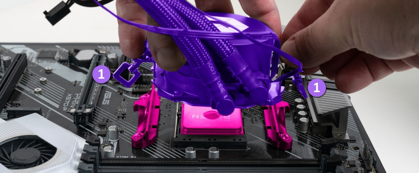
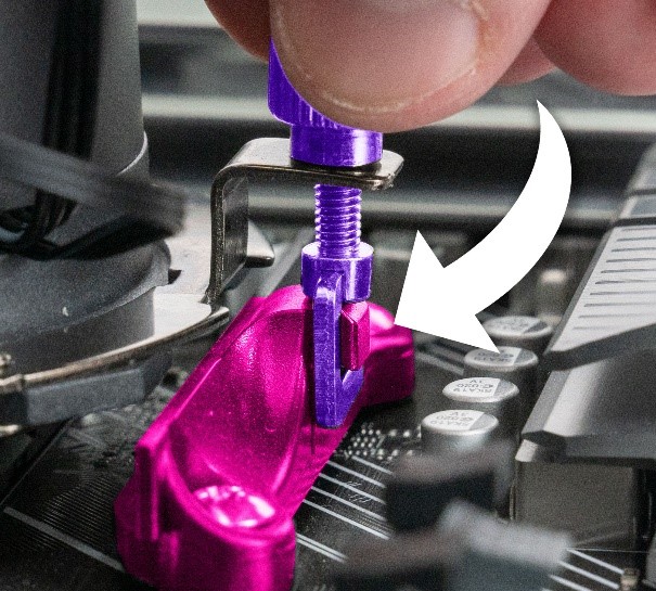
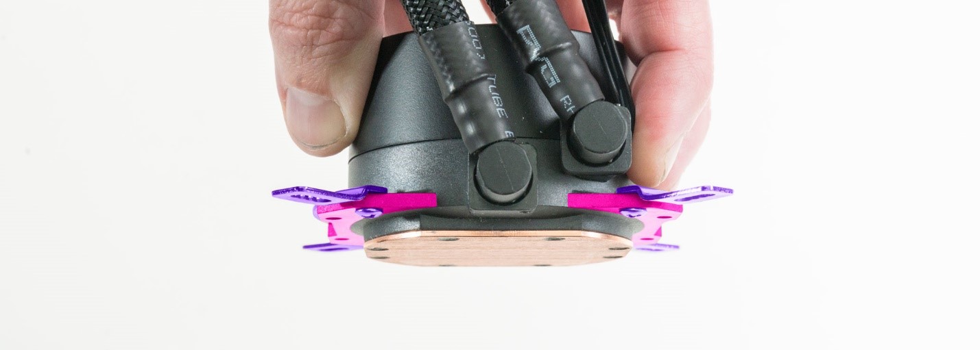
STEP 24: Grab the pump body with one hand and the top screw with your other hand.
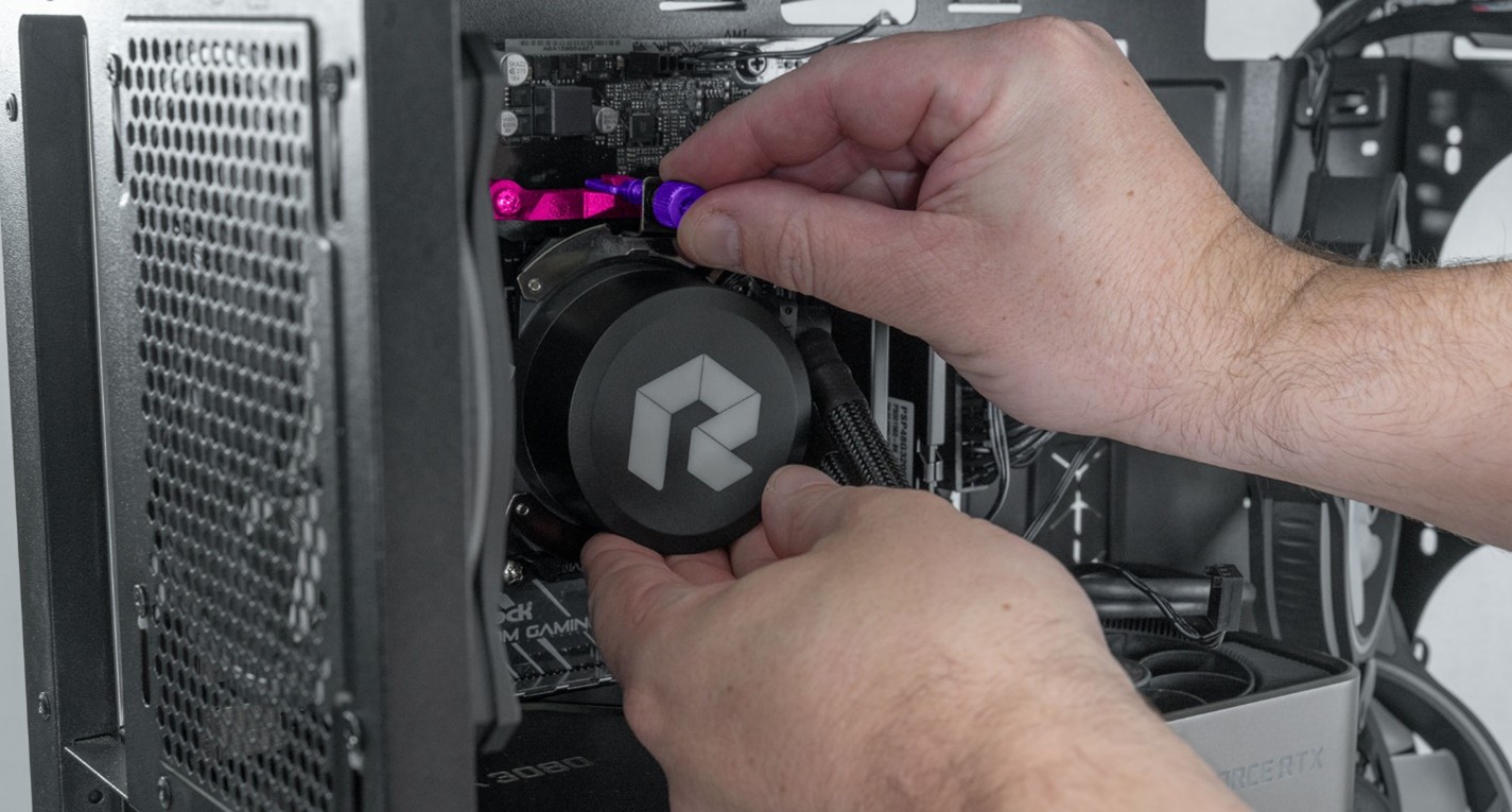
Gently move the pump upwards and rotate the top screw back as seen below. This will unclip the screw from the mounting bracket.

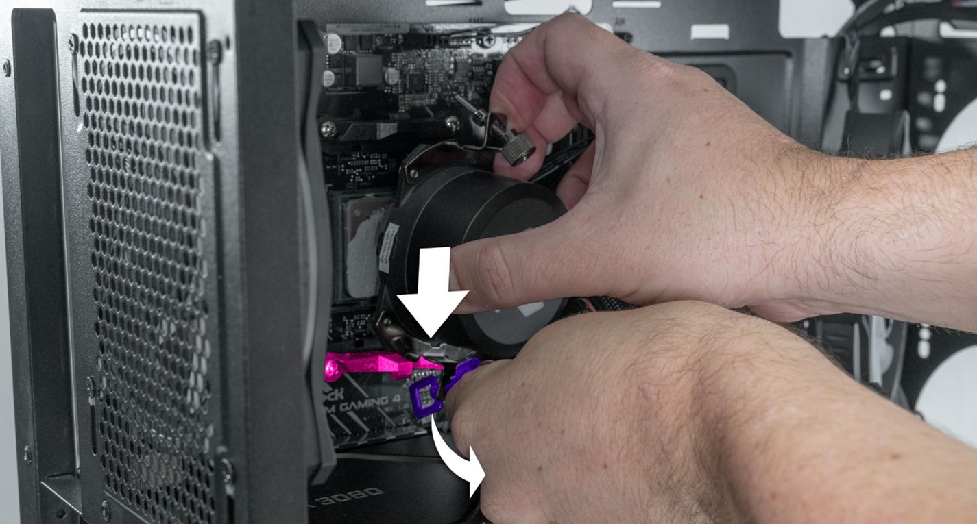
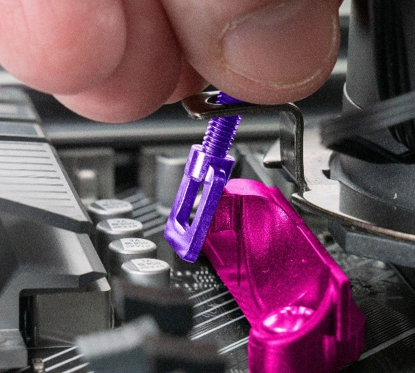
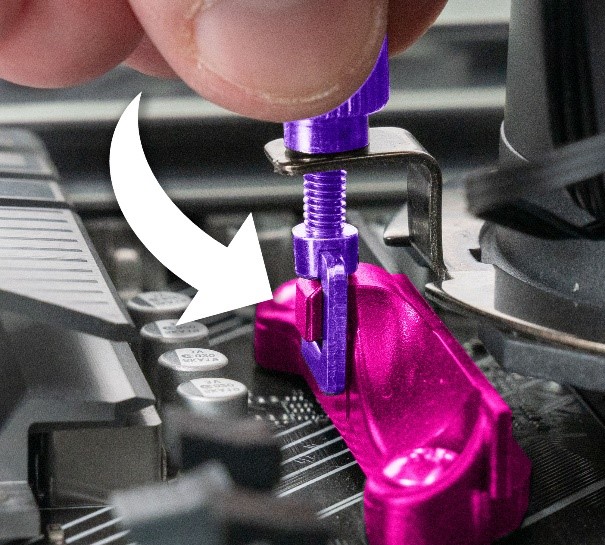
STEP 25: With the top screw unclipped, grab the pump body with one hand and the bottom screw with your other hand.

Move the pump downward while swinging the screw back until the screw unclips from the bottom bracket, as seen in the below photo.
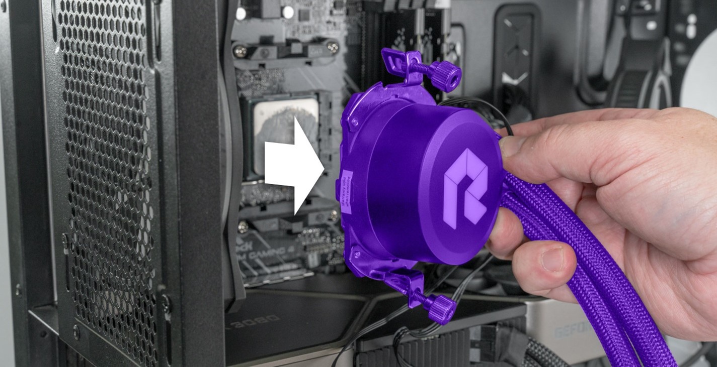
STEP 26: Once both screws are detached, gently try to pull the pump away from the CPU. If your pump feels stuck to the system and does not want to come loose, proceed to the next step. *Do Not Yank on the pump. This could pull the CPU out with the cooler, damaging your PC.
*NOTE* If the pump feels stuck to the system, first verify both clips are unclipped, and the pump is not getting caught by its wires.
If everything looks clear, gently grab the pump body, and rotate it slowly side to side. Don’t move it more than a half inch in any direction while rotating. While doing this, gently pull the pump body, straight back form the mainboard. This is the best way to break the seal formed between the PC and cooler by the dried thermal paste.
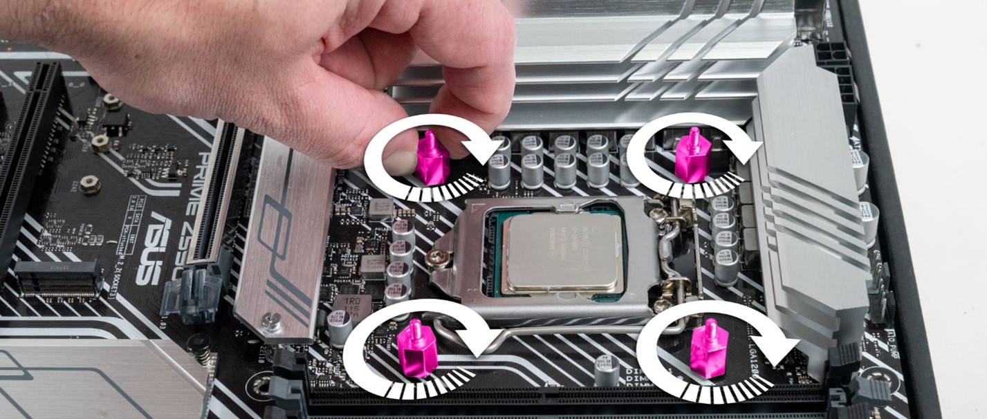
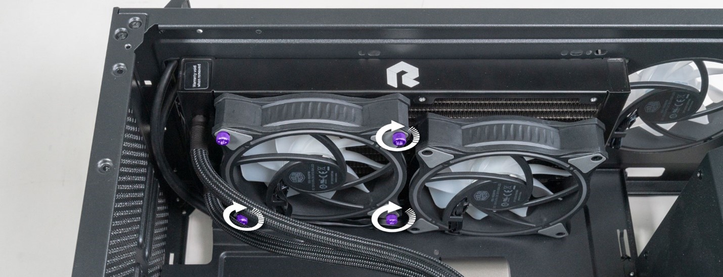
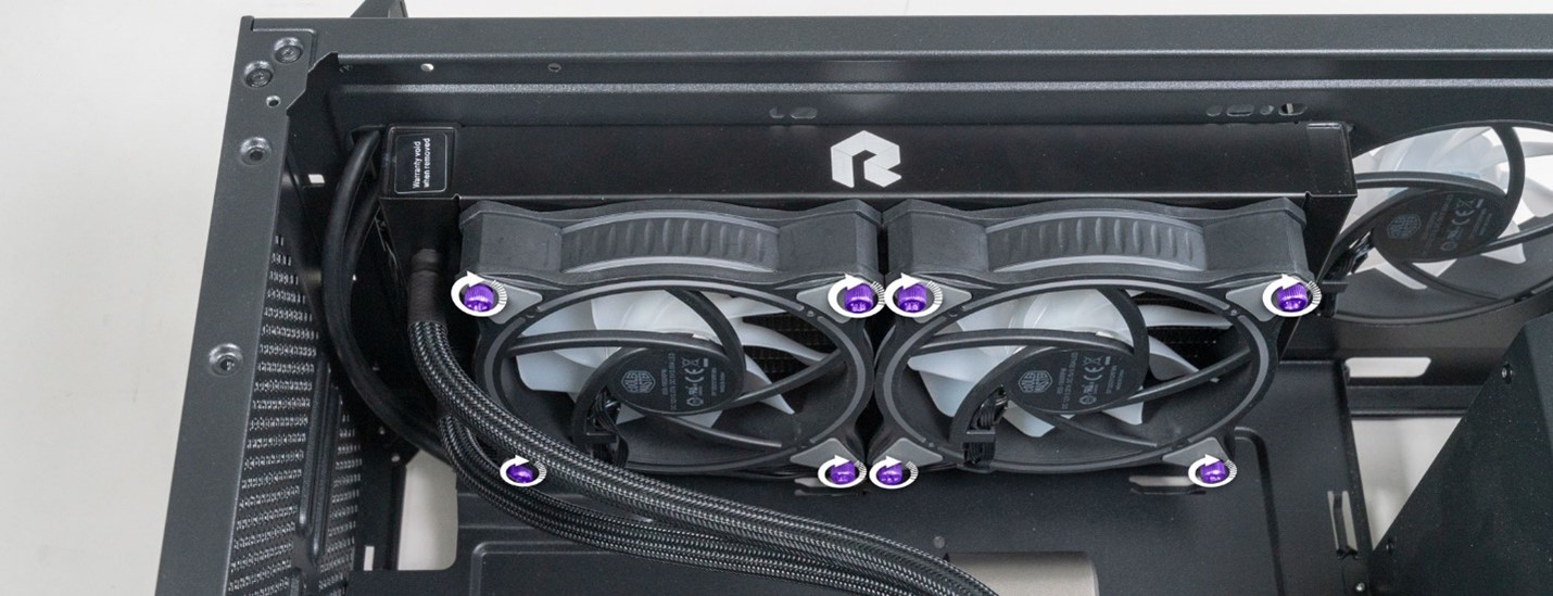
STEP 27: On Intel Systems there are 4x metal screws that hold the pump onto the mainboard. It’s best to remove these in a cross pattern to relieve pressure on the CPU evenly.
*NOTE* Hold the pump with your other hand while removing the last 2 screws. Pressure from the liquid cooling tubes can cause the pump to move in unpredictable directions.
Hold the pump body firmly while removing the last 2 screws.
STEP 28: Gently pull the pump body away from the CPU
Set your old AIO liquid cooling system safely off to the side.
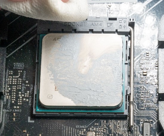
STEP 29: Now we need to clean the old thermal compound off your CPU. Place the PC on its side to make cleaning easier.
With the system on its side the thermal paste is easier to remove.
We will need Paper towel and Isopropyl alcohol. Grab a sheet of paper towel and fold it into a square.

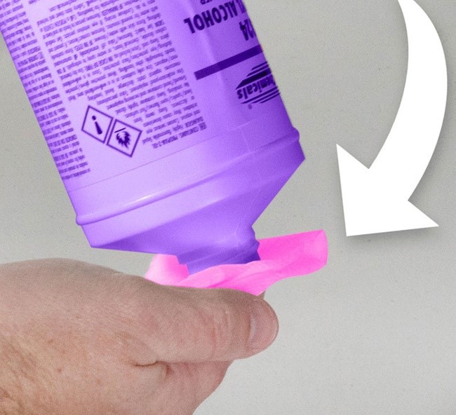
STEP 30: Open the Isopropyl bottle. Cover the opening with your paper towel square and invert the bottle for a moment *NOTE be sure to do this away from your PC or other electronics in case of spillage.

 |
 |
|
Too much isopropyl. This towel is way too wet. |
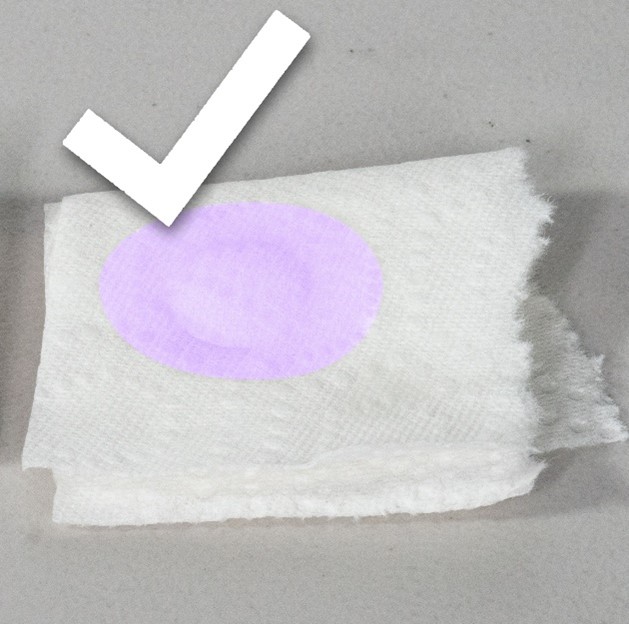
This towel has a good amount of Isopropyl but not too much. Its damp but not dripping. |
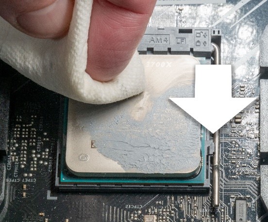
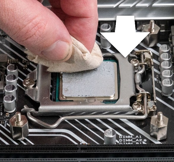
STEP 31: When removing thermal paste, it’s important to prevent the paste from getting on any other components while doing the removal. Some pastes are electrically conductive and can short out your PC if they get on components.
 |
 |
| Damped your paper towel |
Start from the CPU edge and slide inward toward the center. This helps prevent paste from being pushed over the edges of the CPU. Fold your paper towel piece over to reveal a clean piece of paper and repeat this process until the thickest paste sections are removed. |
 |
 |
|
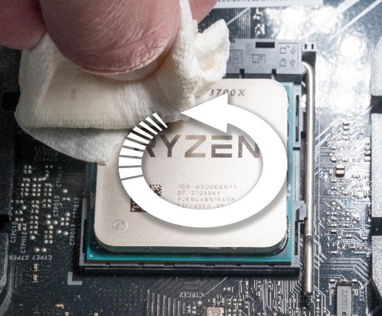
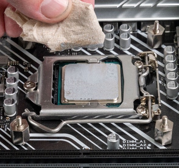
If there is too much paste on your towel, grab a new one and re dampen it. Once the thickest paste is removed, work the towel in a circular motion along the surface of the CPU. |
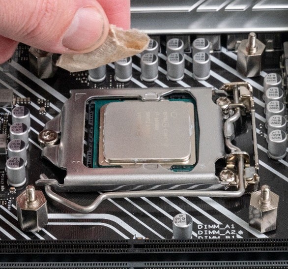
Repeat this process until the CPU surface is clean. When the CPU looks clean, grab a new piece of damp paper towel, and give it one final cleaning. |
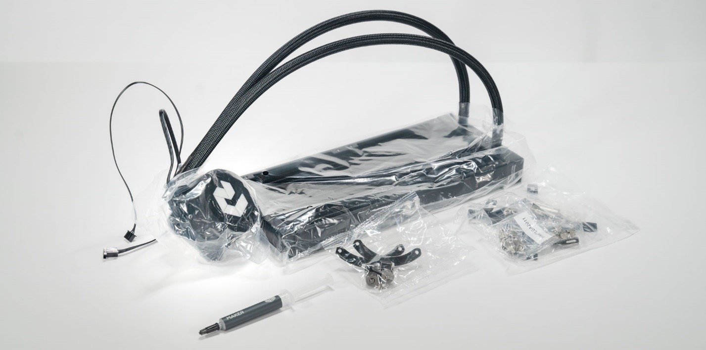
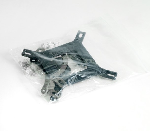
STEP 32: Next, we need to prepare the new liquid cooler for installation. Your replacement cooler should come with multiple mounting brackets and a tube of thermal paste. You will need to install the correct bracket type for your CPU.
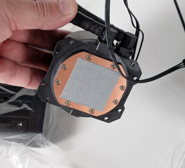
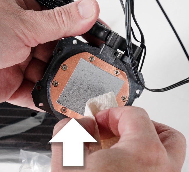
STEP 33: Before attaching the brackets, we need to prepare the Pump’s Copper cold plate surface. Most AIO coolers come with a pre applied patch of thermal paste from the manufacturer. We highly recommend removing this paste and applying your own later in the process. When done properly, this gives the most effective cooling.
 |
 |
| Remove all protective plastic from the CPU pump/ cold plate | Dampen a new piece of paper towel |
 |
 |
| Remove the pre-applied thermal paste in the same way you removed the old paste from the CPU. This paste is a bit drier and thicker so it may take a little more time to remove. | Continue wiping the pump cold plate in a circular motion until all thermal paste is removed and the entire cold plate is shiny copper. |
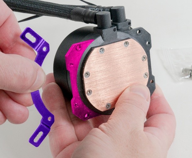
STEP 34: With the cold plate prepped, we need to attach the correct brackets for your CPU type. The easiest way to determine this is to look at your old cooler and select the brackets that look identical. You can also look on your system order sheet.
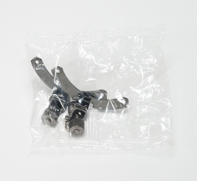
Below is a closeup look of the brackets. We only need to use the bracket that fits your system.
 |
 |
| Brackets for AMD CPUS | Brackets for Intel CPUS |
To install AMD brackets:
 |
 |
| Grab one of the brackets and orient as shown above, next to your AIO pump | Place the metal bracket on top of plastic flange as seen above. |
 |
 |
|
Insert the two Phillips head screws into the mounting holes from the bottom side of the flange and screw them into the bracket. |
Repeat this same process for the other side. |
This is what the assembled bracket will look like. Compare yours with the below photo to verify everything was installed in the correct way.
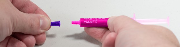
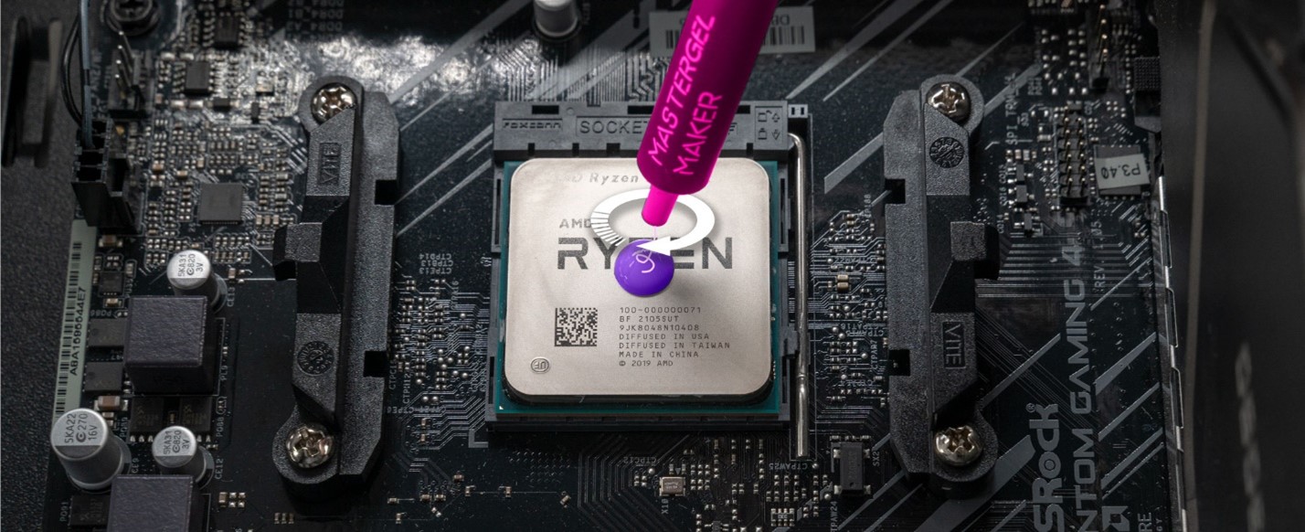
STEP 35: It’s time to apply our new thermal paste to the CPU.
Gently uncap the thermal paste tube *NOTE* due this away from your computer, preferably over a paper towel. Some tubes may have a pressure difference, causing paste to come out after uncapping. If a lot of paste comes out, pull back on the paste syringe.
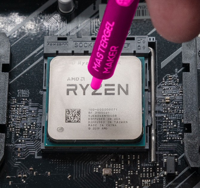
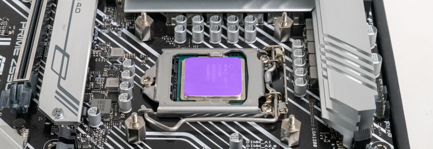
STEP 36: Now we can apply the thermal paste. Make sure your CPU surface is clean and has no hairs, dust, or obstructions on it. The below CPU is clean and ready for thermal paste.

 |
 |
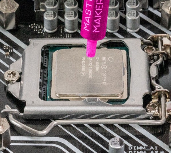
| Hover your syringe directly over the center of your CPU |
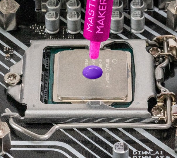
Slowly squeeze thermal paste from the syringe until a drop the size of the one above is present. The goal is to make a dot that will flatten out and touch all 4 corners when the pump is pressed into the CPU. |
There will usually be a thin stringy section of thermal paste connected from your paste dot to the syringe. To break this, spin the syringe in a circle a few times over the thermal paste dot until this string breaks.
Do not immediately pull the syringe away form paste. It will usually cause a thin line of paste to drip over your mainboard. This may cause damage.
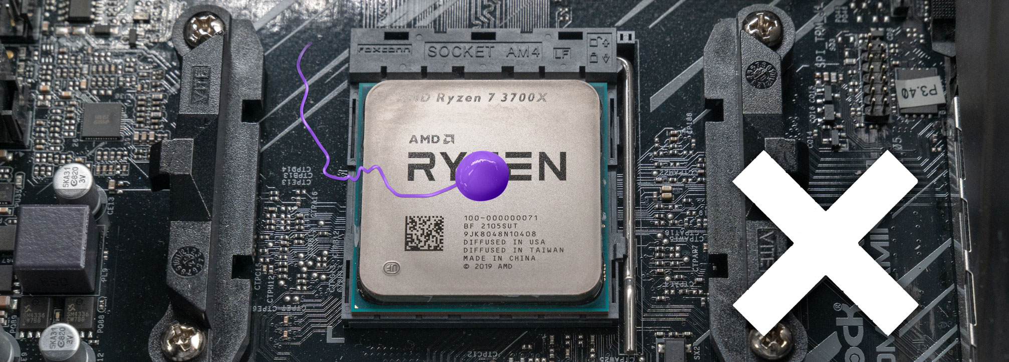
Once finished applying paste, swirl syringe above thermal paste dot until string breaks, then remove syringe.
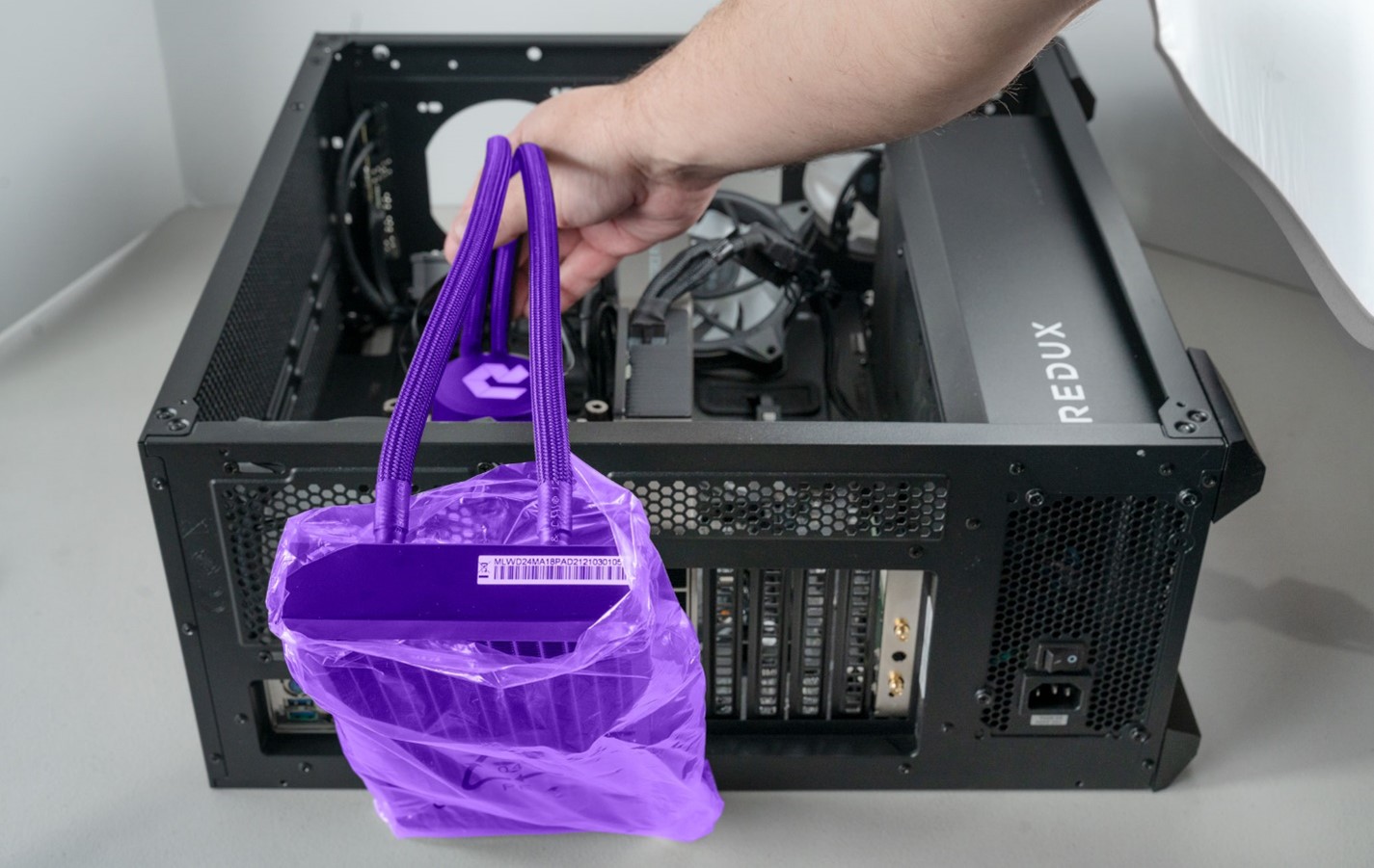
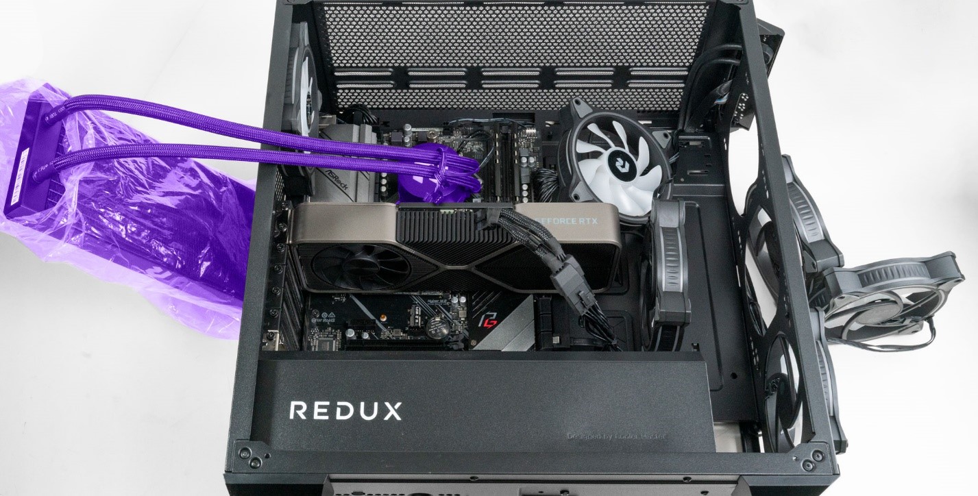
STEP 37: We are now ready to attach the pump. In this PC We find it easier to connect the pump first and then the radiator second. Keep the plastic bag over your radiator to prevent it from scratching the case. Place the radiator along the back side of your case as seen below.
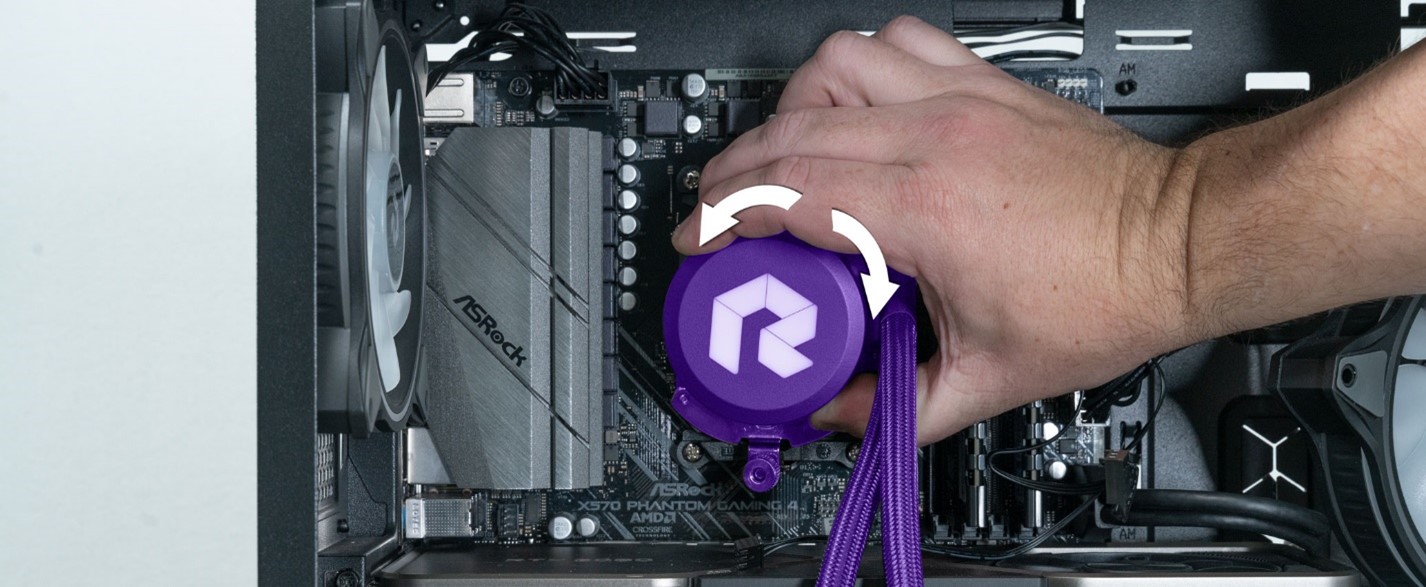
*NOTE* Make sure the Build Redux “R” on the pump is oriented so it’s facing the correct direction when your PC is finished.
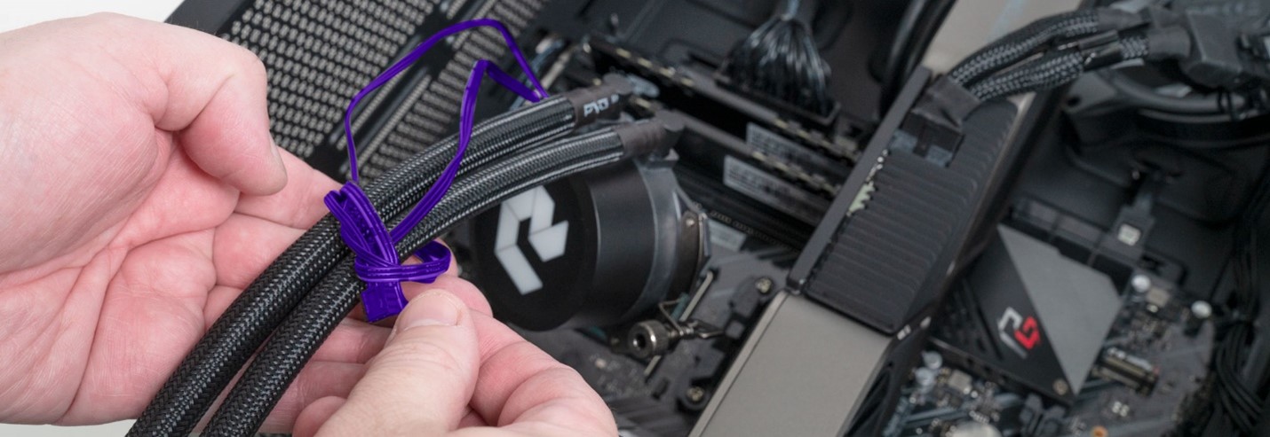
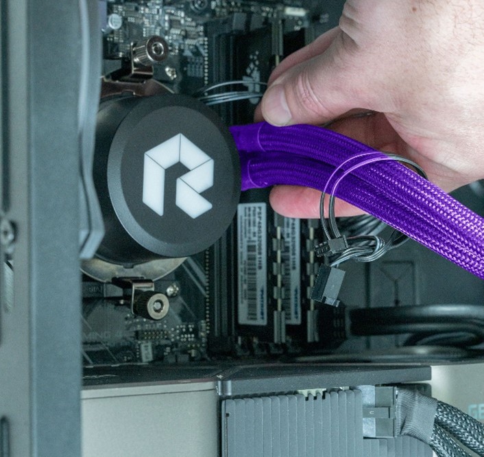
STEP 38: Before we lower the pump into the system for installation, loosely tie the cables coming from the pump to the liquid cooling tubes. This will temporarily keep them out of the way while we work on mounting the pump to the mainboard.
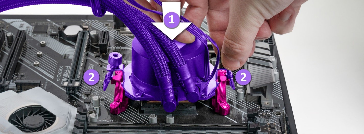
STEP 39: Hold the pump above the CPU and brackets. *NOTE* Make sure no cables are running underneath the pump.
- Make sure the mounting brackets on either side of the pump are not underneath the pump.
STEP 40: Keep the pump level and gently press it onto the top of the CPU. Do your best not to slide the pump side to side once it is placed on the CPU. It may move a little as you align the brackets but try to keep this to a minimum.
*NOTE* Do not pull the pump off the CPU unless necessary. This will disturb the thermal paste application and introduce air bubbles, potentially making it less effective. If this happens its best to clean both the pump and CPU and reapply the thermal paste from scratch.
Do not gently touch pump to paste then remove it. Once ready to install the pump, you really need to commit to it. If you lightly touch the thermal paste with the pump bottom, then remove it without flattening down the paste, It can cause a long thin line to follow the pump, dripping all over the board.
- Keep the pump level and gently press it into the CPU.
- Make sure the bracket looks like this and is not trapped between the pump body and base plate.
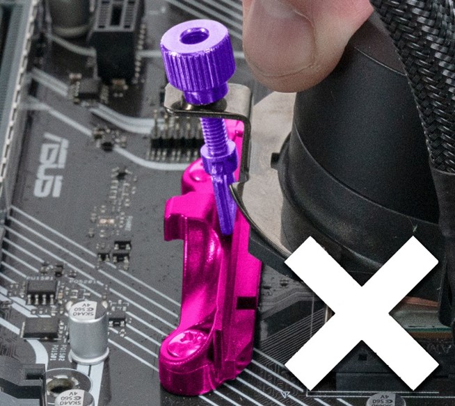 |
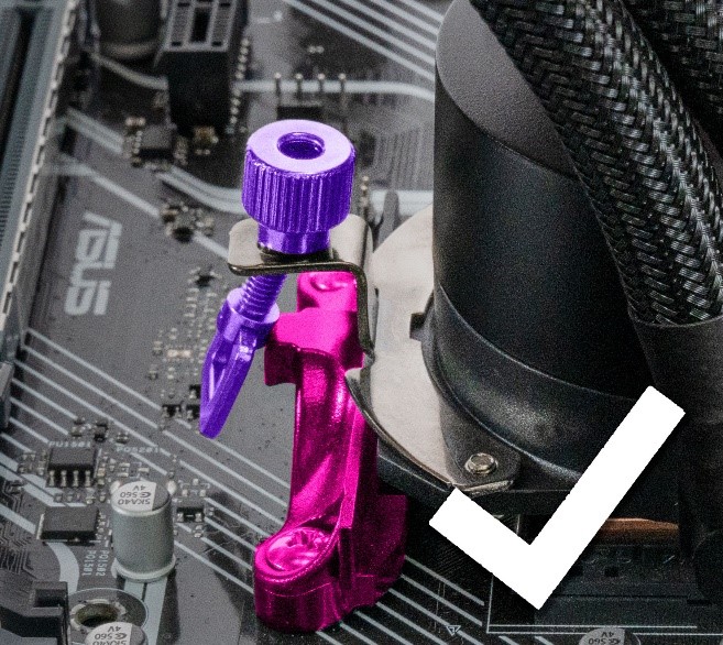 |
| Bracket trapped between pump and base plate. This will make it impossible to mount the pump. | Bracket correctly positioned on outside of base plate. |
STEP 41: With one hand continuing to hold the pump down against the CPU, use your other hand to clip the bracket to the base plate.
 |
 |
| Position the bracket like so. |
Rotate the bracket until it clips into the tab on the base plate. Make sure the bracket is fully clipped in as seen above. |
 |
 |
|
Repeat this process for the other side, positioning the bracket like so. |
Rotate the bracket until it clips into the tab on the base plate. |
STEP 42: Continue holding the pump with one hand and start tightening the first screw. Only tighten it a few turns, then move onto the second screw.
Go to the 2nd screw and tighten it a few turns. Continue this process going back and forth. This helps to apply pressure evenly, giving the thermal paste an even application as the pump tightens.
Repeat this process until the screws are fully tightened. Inspect both screws and the angle of your pump. Make sure both screws are being tightened equally. If one screw is tightened more, the pump will appear at a slight angle. Remedy this by tightening the opposite screw until the pump levels out. As the screws get tighter it does require a bit more force to tighten them. You should eventually get to a point where the screws become too difficult to hand tighten much further. This should be a sufficient point to stop.
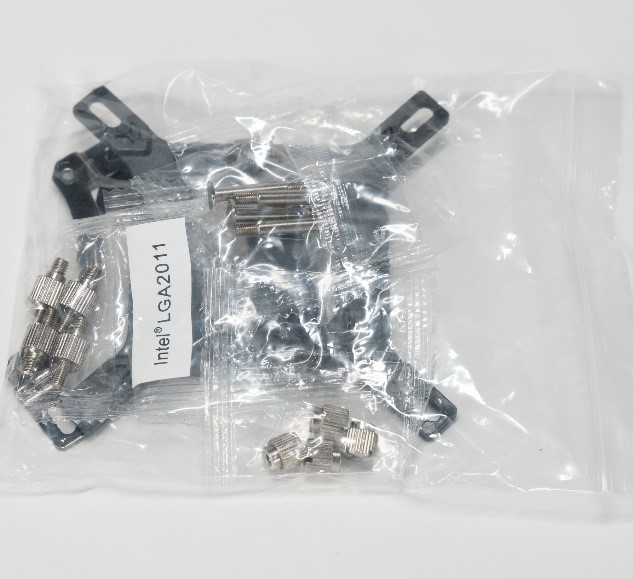
STEP 43: To install Intel brackets:
 |
 |
| Grab the intel brackets bag. | Remove only the above items. |
STEP 44: Grab one of the two brackets. They are identical so it does not matter which one you grab. Hold it up to the pump as seen below. Notice how the two tabs are indented downwards. Make sure your bracket orientation matches the below photo.

 |
 |
| Align the bracket to the pump base. | Put the bracket on top of the base plate. |
 |
 |
| Screw in the 2x Phillips head screws into the bracket from the bottom. | Repeat this process for the other bracket. |
Below is a photo of the completed Intel bracket assembly. Verify your installation matches the below photo.
STEP 45: Check the mainboard stand offs and tighten them down. Usually at least one of these will be loose from when the original cooler was removed.
STEP 46: Open the Isopropyl bottle. Cover the opening with your paper towel square and invert the bottle for a moment *NOTE be sure to do this away from your PC or other electronics in case of spillage. 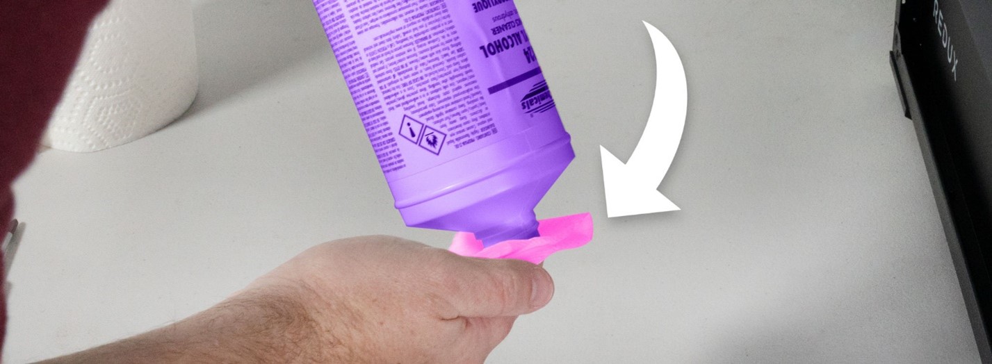
You don’t need very much. Just enough to dampen a small section of the towel. You do not want it to be dripping wet.
 |
 |
| Too much isopropyl. This towel is way too wet. | This towel has a good amount of Isopropyl but not too much. Its damp but not dripping. |
STEP 47: When removing thermal paste, it’s important to prevent the paste from getting on any other components while doing the removal. Some pastes are electrically conductive and can short out your PC if they get on components.
 |
 |
| Take your dampened paper towel and wipe the CPU, starting at the edge and working toward the middle. This prevents thermal paste from being pushed off the CPU. |
Repeat this process wiping from the edges toward the center. Grab a new piece of dampened paper towel after a few wipes or the paste will start to gum up the towel. |
 |
 |
| Once most of the thermal paste is removed, grab a new damp paper towel, and gently rub the CPU surface in a circular motion. |
Once clean, grab one more damp paper towel and wipe down the CPU surface one more time to fully remove the last bits of thermal paste. |
STEP 48: Now we can apply the thermal paste. Make sure your CPU surface is clean and has no hairs, dust, or obstructions on it. The below CPU is clean and ready for thermal paste.
 |
 |
| Hover your syringe directly over the center of your CPU |
Slowly squeeze thermal paste from the syringe until a drop the size of the one above is present. The goal is to make a dot that will flatten out and touch all 4 corners when the pump is pressed into the CPU. |
There will usually be a thin stringy section of thermal paste connected from your paste dot to the syringe. To break this, spin the syringe in a circle a few times over the thermal paste dot until this string breaks.

STEP 49: Align the cooler’s pump above the 4 mounting pegs on the mainboard
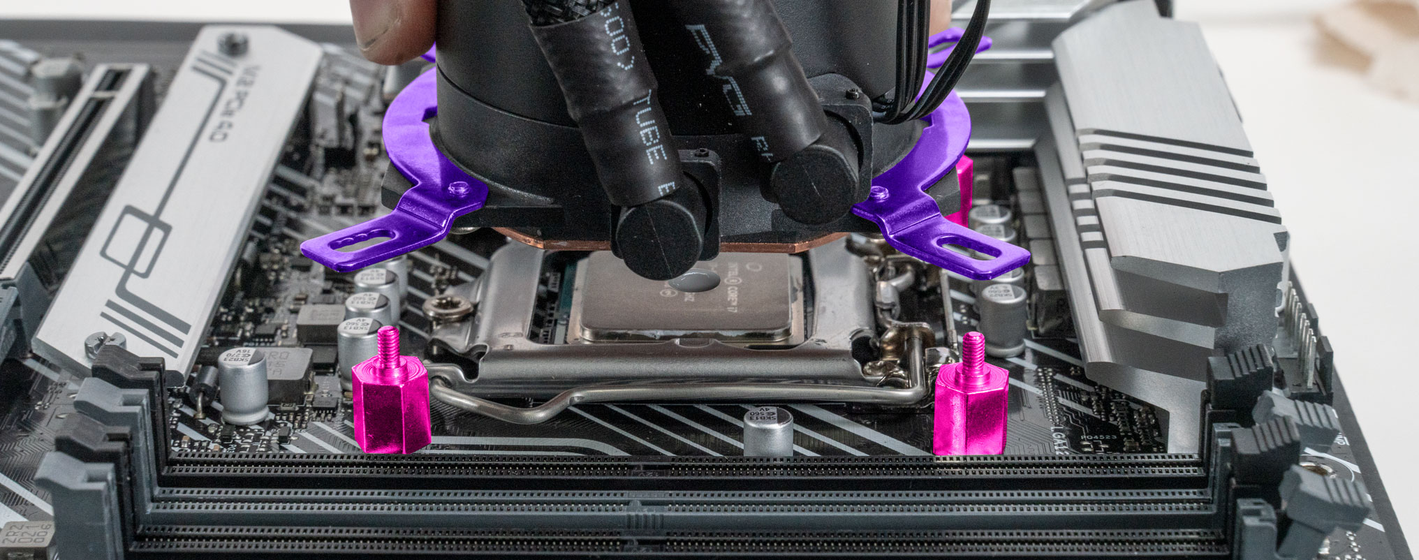
STEP 50: slowly and evenly press the pump into the CPU, making sure all 4 pegs fit through the bracket.
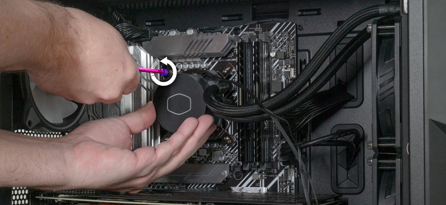
STEP 51: Continue holding the pump with one hand to prevent it from lifting off. Use your other hand to screw on the first mounting screw.
Continue holding the pump in place and install the next mounting screw, diagonally across from the first one you installed.
You can let go of the pump at this point and install the other two screws one at a time.
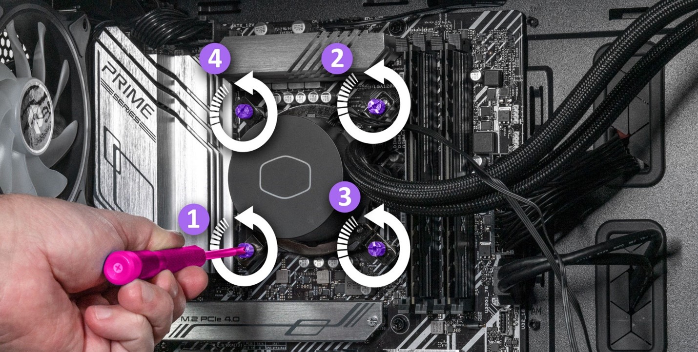
STEP 52: With all 4 screws installed, go back with a screwdriver and finish tightening them in a cross pattern as seen below.
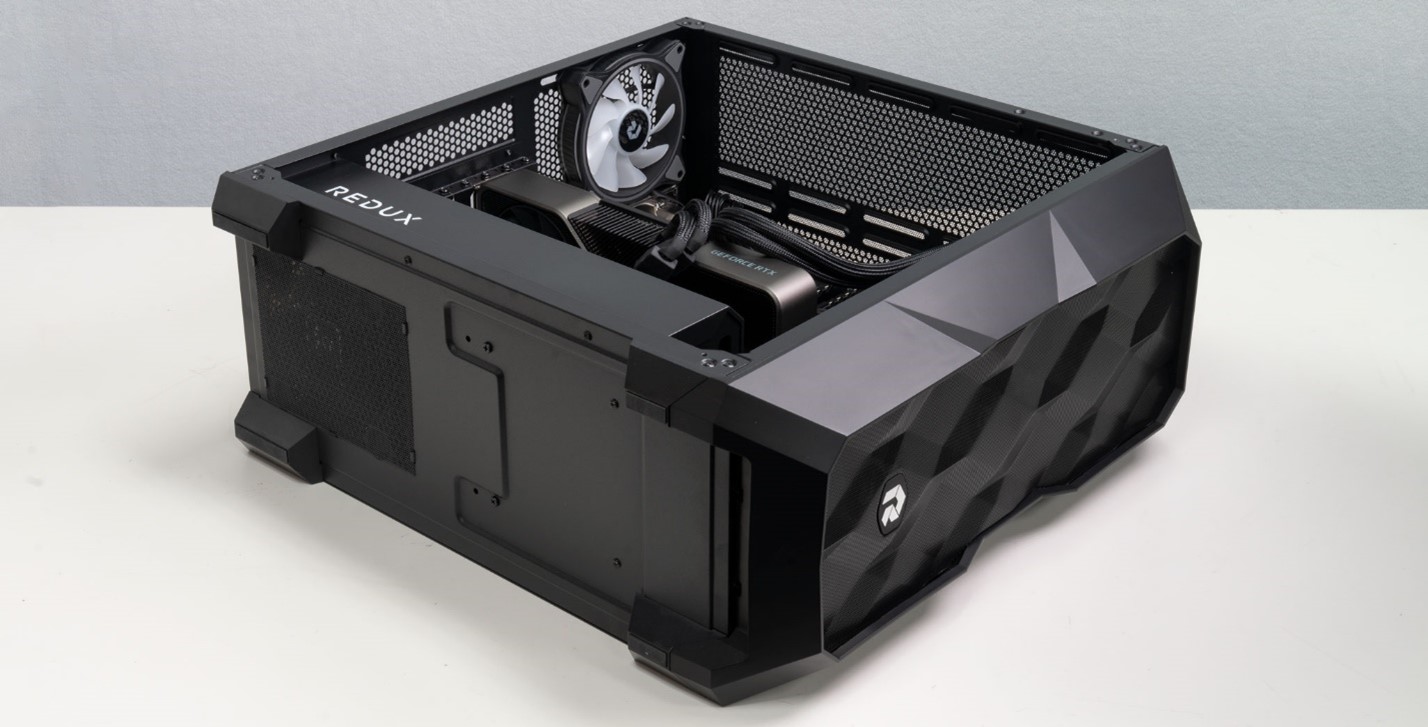
STEP 53: Your system should look like the below photo now.
STEP 54: pick up the radiator remove the plastic wrapping. With the radiator in one hand, move on to the next step.
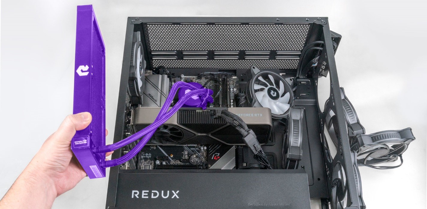
STEP 55: Before mounting the radiator, we need to angle the liquid cooling tubes downward.
 |
 |
| While holding the radiator with one hand, use your other hand to gently grab the base of the liquid cooling tubes, next to the pump. |
Angle the tubes down slightly toward the video card. This will help to position the radiator in the next step. |
STEP 56: Gently pick up the radiator. Carefully and slowly rotate the radiator as seen below, make sure the tubes coming out of the radiator are on the right side.
Continue carefully rotating the radiator until it is in the below position with the tubes on top.
STEP 57: While aligning the radiator, gently pick up the interior fans and place them against the radiator as seen below. It’s best to get these roughly in to position now so they don’t get trapped under the liquid cooler tubing when we attach the radiator in the next step. *Note* Make sure the side of the fan with all the legalese and fine print is mounted outward so you can see it, as seen below.
The fan cabling should be on the bottom of the fan, underneath it. This hides the wiring, making the system look cleaner.
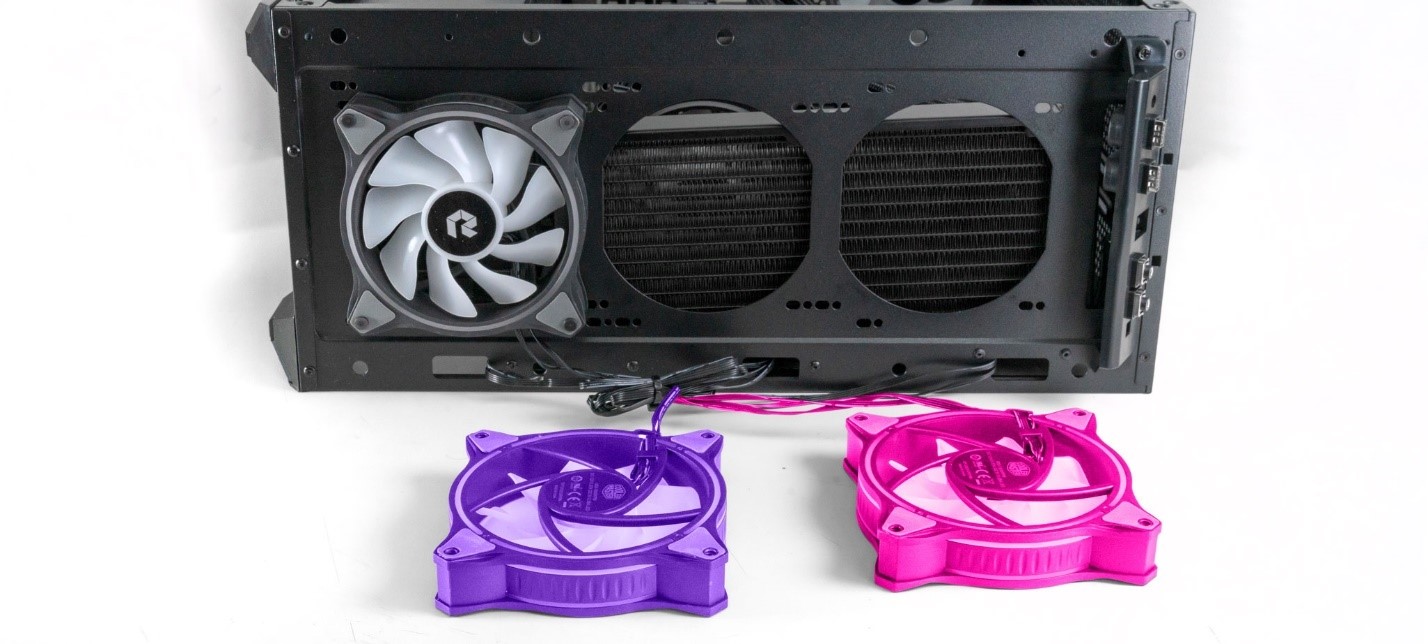
STEP 58: Lay out the two front fans and arrange them so they each have enough cable slack to attach to the case. If one fan can’t reach, you likely need to swap them around, or check and make sure the cabling is not caught or tangled up on anything.
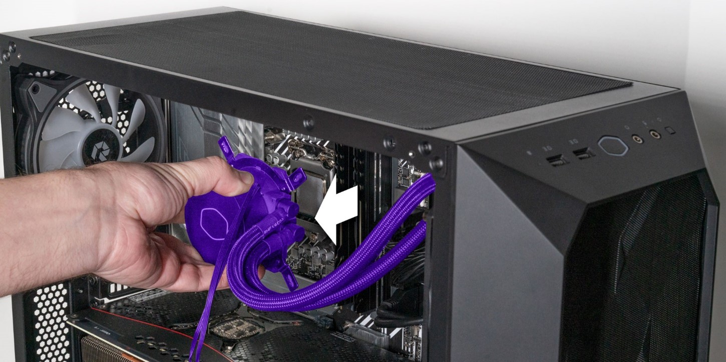
STEP 59: With the fans oriented, Hold the radiator up against the front of your PC. *Note* make sure the 2x interior fans and their cables are not trapped between the radiator and case.

STEP 60: the Radiator has 8 holes in it that we need to align with 8 holes on the case. There are multiple holes sized for different size fans. Your radiator will only fit on the inboard set of holes that align with the installed case fan.
On that inboard row There are two sets of holes, one round and one oval shaped. The correct set to use is determined by which set the existing case fan is installed in. ours is installed in the small round holes so that’s what we will use for our radiator.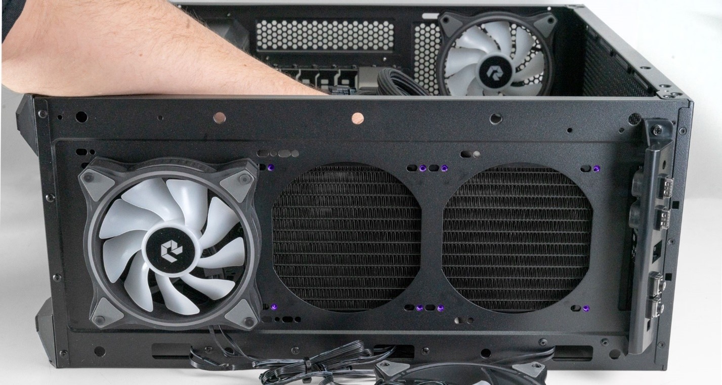
STEP 61: Grab the middle of the three fans and orient is as such with the fully exposed fan blades facing toward you and the cables coming out of the fan located along the bottom.
STEP 62: With our fan oriented correctly, grab one of the long radiator mounting screws and thread it through the top left hole in your fan.
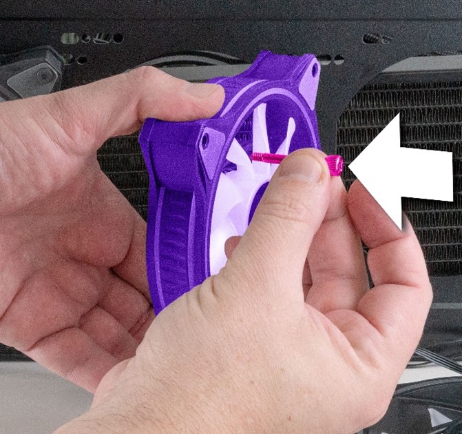 |
 |
| Thread one of the long radiator mounting screws through the top left hole in your fan. | Push it all the way through. |
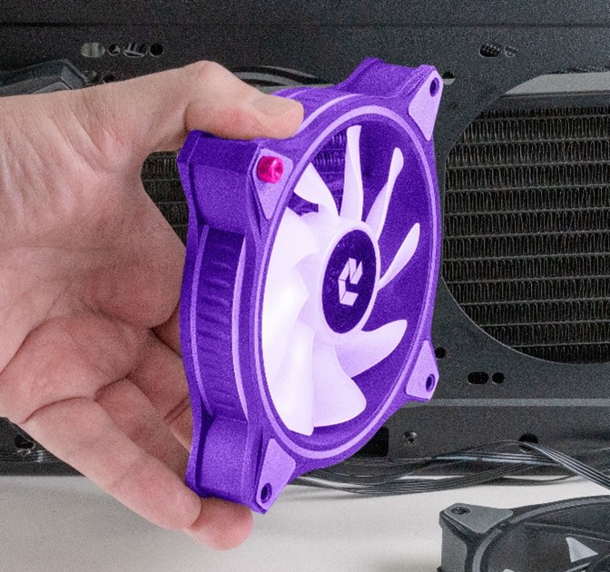
STEP 63: align the top left hole on your radiator This is where we will attach the first fan screw.
STEP 64: Continue holding the radiator in place and align the first screw with the radiator
 |
 |
| Align and tighten the screw down with your fingers. | Continue holding the radiator and install the bottom right screw. You may have to angle the radiator up or down a bit until it’s hole aligns with the screw. Once aligned, tighten the screw down by hand. |
STEP 65: Install and tighten the 2x remaining screws so all 4 screws are connected. *Note* if you are having trouble getting a screw to align, gently loosen the other screws a few turns to give the radiator some play. You then should be able to move the radiator and fan around enough for the holes to align.

STEP 66: Repeat this process for the next fan.
 |
 |
| Make sure the fan blades are oriented correctly and the cable is located on the bottom. *Note* on some builds, if wiring is tight, its okay to rotate the fan 90 degrees to the side that gives the most slack. | Screw in all 4 mounting screws in the same manner as the previous fan. |
STEP 67: Use a Phillips head screwdriver to tighten all 8 Radiator fan mounting screws. *Note* these need to be snug enough to hold the radiator to the case but not extremely tight. If these are over tightened, you will see the fan tabs bending, which may cause damage to the fans.
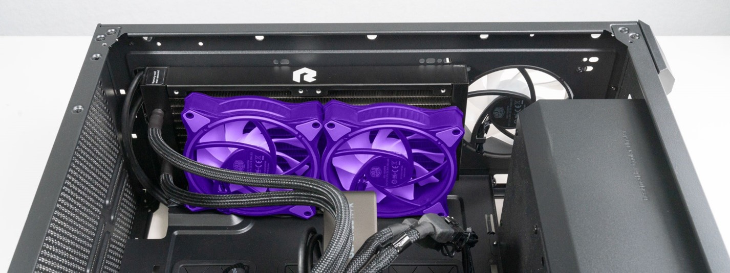
STEP 68: Now we need to install the 2x radiator fans on the inside of the system. Check on the fans to make sure they are oriented as seen below, with the fan motor mount and small legalese visible.
STEP 69: Let’s start with the top radiator fan first (left fan as seen in our pictures.) Repeat the same process we used for the front fans.
 |
 |
| Insert a fan mounting screw into the top left hole on your fan. | Push the screw all the way through. |
 |
 |
| Align the fan and screw with the top left screw hole on the radiator. | Screw in the first fan screw. |
STEP 70: Screw in the other 3 screws. Its easiest to do the 2nd top screw first, then move to the two bottom screws. Just like the front, if you have a screw that won’t fit, unscrew all screws on that fan a few turns to loosen them and give some wiggle room.
STEP 71: Repeat this process on the second fan.
STEP 72: Go back and tighten all 8 screws by hand until the screws are difficult to turn. Since the screws are only holding the fan to the radiator, it’s not necessary to tighten them further with a screwdriver.
STEP 73: Now we can run our pump LED and power cables. Start with the LED cable. This is the smaller connector of the two.
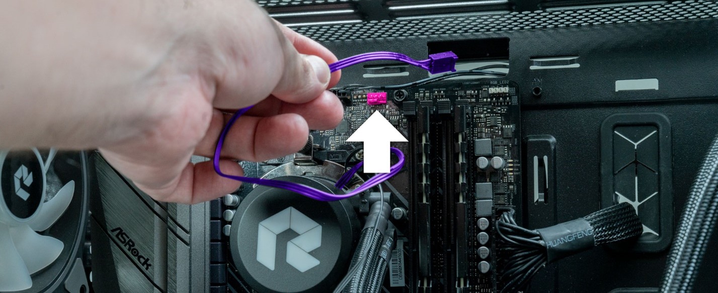
STEP 74: Push the pump LED cable through to the other side of your system.
 |
 |
| Pull the cable down and under the larger thicker cables. | Plug the cable into the open LED connector it was originally unplugged from. |
STEP 75: if you have a non Build Redux branded cooler, reinstalling the LED connector is slightly different. The LED connector on this cooler is much larger and has 4 holes on the end.
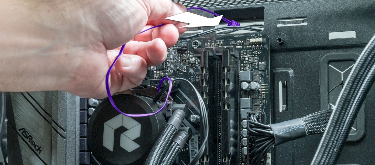
STEP 76: Snake the LED cable through to the back side of your PC.
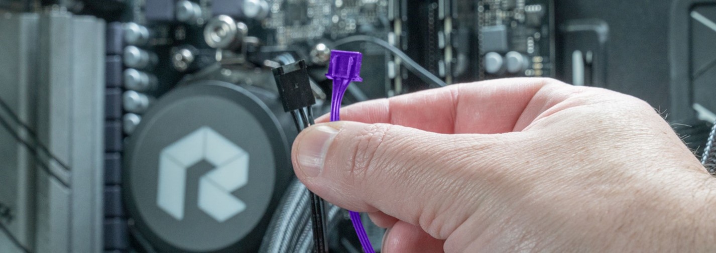
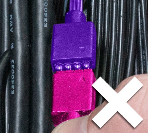
STEP 77: Find the male connector we disconnected it form earlier. There is a small arrow on each connector. When you connect them. These arrows must be aligned.

 |
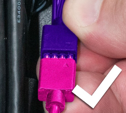 |
| Make sure you are plugging the pins into the connector and not the surrounding plastics. It’s fairly easy to do. | These pins are properly connecting with the connector. |
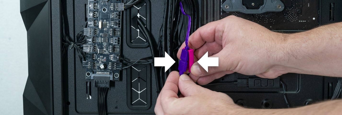
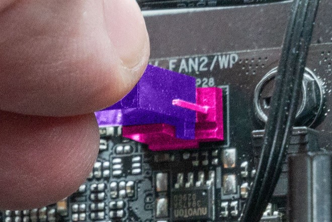
STEP 78: press the two sections together and press on the plastic cover.
Step 79: Position the connector cleanly in your wire bundle and add a zip tie to keep the wiring tidy.

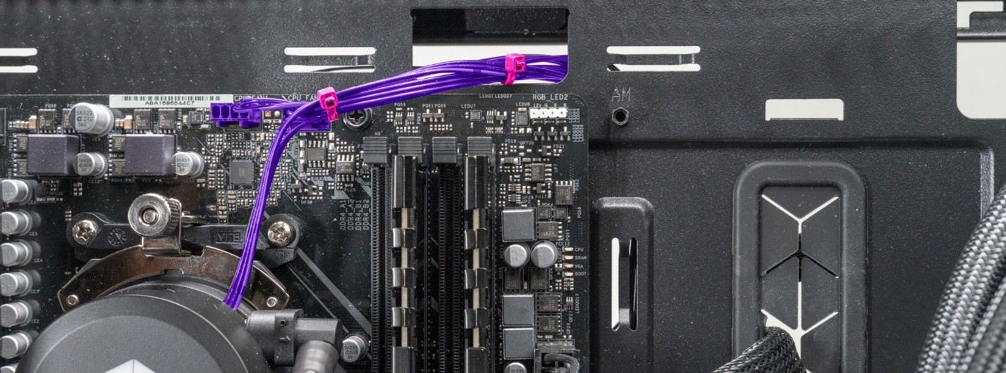
STEP 80: Next up is our pump power cable. This can run to several different places depending on the mainboard in your PC. We need to plug this back in to the same connector it came from. Labeled AIO PUMP on most boards.
On some systems it is below and to the left of the cooler. In these configs, we usually run the cable around the mainboard heatsinks to cleanly take up slack. Cleanly run the wire and add zip ties where necessary to clean up wiring.

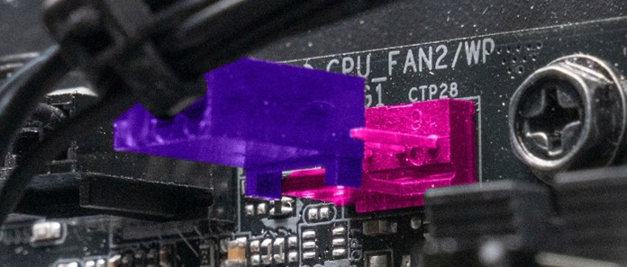
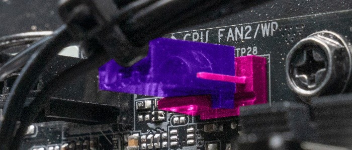
In our example system used for this guide, the connector is located directly above the pump. This system has it labeled as CPU FAN2/ WP
STEP 81: Plug the cable in first. We will cleanly run the cable in the next step.
 |
 |
| Plug the CPU pump cable into the mainboard header. | Most pumps have a 3-pin connector, but the mainboard header has a 4th pin that will remain exposed. This is normal. |
 |
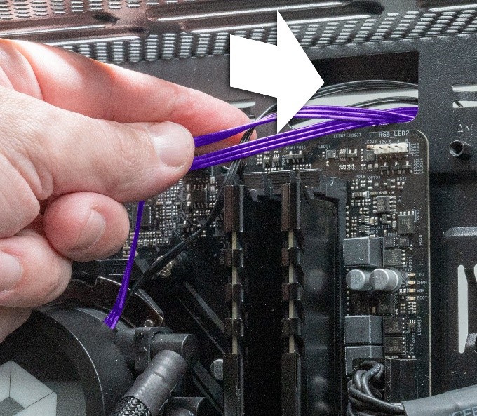 |
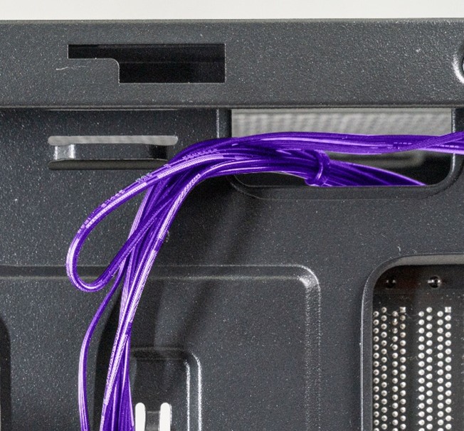
| Make a loop out of the excess pump wiring as seen above. |
Push the end of this loop through to the back side of the system. |
STEP 82: Gently gather all the cable along the top of the system together and zip tie them cleanly together.
STEP 83: Go to the back side of the system and cleanly zip tie the wires as well.
 |
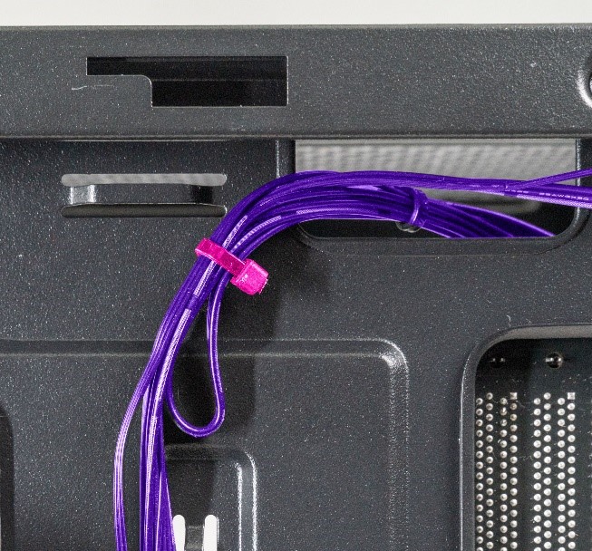 |
| Here is the looped pump cable we pushed through earlier. | Add a zip tie to clean things up. |
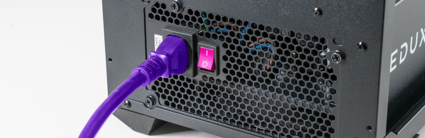
STEP 84: all the core pieces inside of the system should be assembled now. Before we put the front and side panels on, its best to test the system and verify everything is functioning properly. Plug in the power cable and make sure the PSU power switch is set to the I or “ON” position
 |
 |
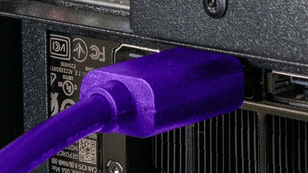
| Plug in your monitor |
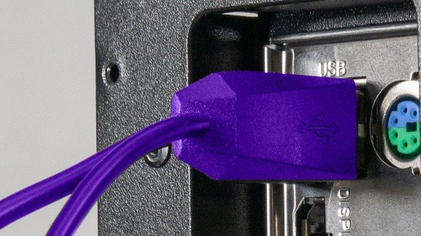
Plug in a keyboard and mouse. |
STEP 85: We need to power the system on and load into bios to check temperatures. This is very important as we want to make sure the new pump is working properly, and the system is not overheating.
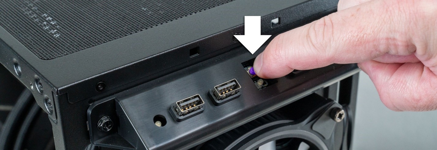
Press the small, indented power button on the top of your PC to power the system on.
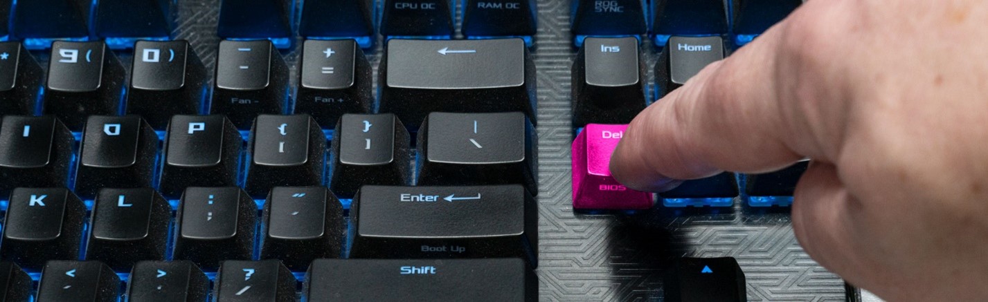
STEP 86: As soon as the system powers on, start pressing the “Delete” key on your keyboard once per second. Keep doing this until the system loads into bios.
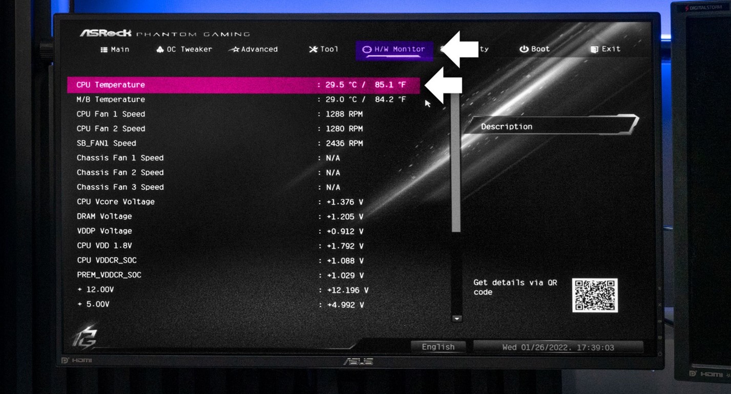
STEP 87: The below system has loaded into bios. This is where we will check system temperatures to make sure the system is not overheating while idling. The look and location of this information will be different based on the hardware in your system, but most Bios have a similar layout.
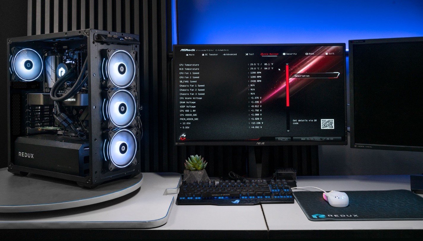
There is no set number we are looking for as idle temps will vary based on your CPU, fan profiles and ambient room temps. We are however looking for a general range.
Intel CPUs tend to idle a bit lower than amd. ----On Intel, temps should be between 20-35C
AMD CPUs tent to idle hotter than Intel. ----On AMD, temps should be between 28-45C
If your temps are noticeably higher than this, say 50-60C+ it indicates there is an issue with the cooling system we need to diagnose.
To Check Bios temps on ASROCK boards, Click on H/W Monitor along the top, then look for CPU Temperature.
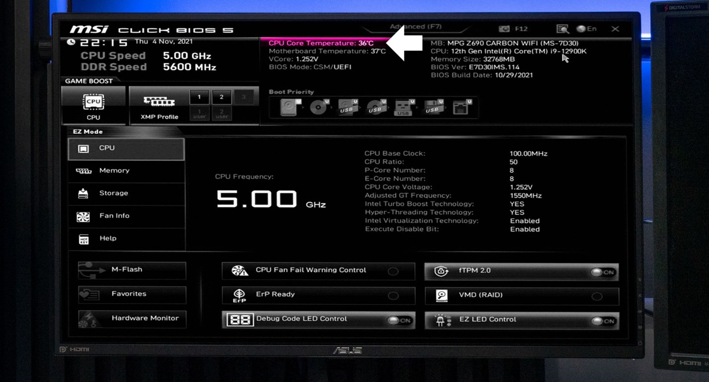
To Check Bios temps on MSI boards, look for CPU Core Temperature at the top middle.
To Check Bios temps on ASUS boards, look for CPU Temperature at the top middle.

If your board looks different than any of the above pictures, look for a section that mentions H/W Monitor, Monitor or PC Health
STEP 88: If your system is above the acceptable temperature ranges, Shut the system off and double check a few items inside your computer.
ON AMD, double check that you tightened both the screws down all the way. Loose screws will cause poor cooler contact with the CPU.
On Intel, double check that you fully tightened all 4 screws.

 |
 |
| The above Pump power cable is barely connected | Make sure the Pump power cable is fully seated on your mainboard and is plugged into the correct Mainboard header. |
Did you apply thermal paste?
If you are still having problems with overheating, there may be another issue causing the issue that is more detailed than this guide can address. please contact our technical support staff. They will be happy to assist with getting your computer fully up and running
Please feel free to contact our support staff at 1-856-390-7905
Or by filling out a support request form at https://buildredux.com/pages/support
STEP 89: If system temps look good, do a quick check on your system. Is the pump lighting up? Are all the fans spinning and lighting up?
Check the 2x interior fans as well.
If everything is lighting up and spinning, we can proceed to putting our system back together. If you have a fan that is not lighting up or is not spinning, go to the back side of your system and locate the LED / FAN control board. Check every connection for loose connectors.

If none of your fans or LEDs are lighting up, the control board power cable is likely loose.
 |
 |
| Sata power cable is loose. | Make sure cable is fully connected. |
 |
 |
| Check all fan power connectors. | Check all LED power connectors. |
STEP 90: It’s time to reinstall the front panel. Grab the panel and hold it in the upright position in front of the case. There are 8 mounting tabs (4 on each side) of the panel that mount into holes on the case.
Before installing the panel, make sure there are no wires blocking the case holes.
 |
 |
| Wires obstructing a hole. This can cause damage if pushed on. | Make sure all Holes are clear of cables before proceeding. |
STEP 91: With all the holes clear, press the panel into the case, press along all 4 corners of the panel until it fully snaps into place.
STEP 92: Grab the back panel and align it with your system. The metal tabs on the top and bottom of the panel will fit into the corresponding slots in your case.
Once seated, gently slide the panel forward. I usually keep my hands positioned roughly in the middle of the panel to help keep panel flat against the case.

Check for any gaps in the panel at the top or bottom.

Tighten the two thumb screws on the back.
STEP 93: Next grab the glass side panel and align its bottom edge with the bottom of your case.
Gently set the glass on the bottom edge of your case.
Align the side panel screws with the holes in your case.
Tighten down both screws.
STEP 94: The cooler installation is now complete. We can now plug the system back in, load it up and start using the system. We recommend downloading temperature testing software and using it to monitor temps while gaming.
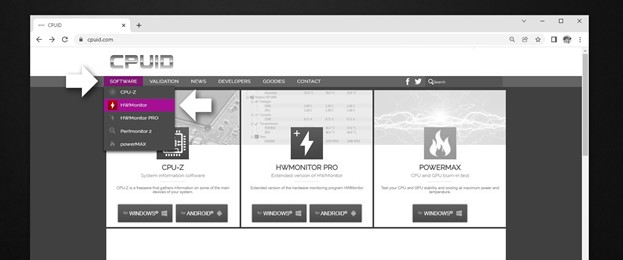
- Open a web browser and go to cpuid.com
- Click on Software at the top
- Click on HWMonitor
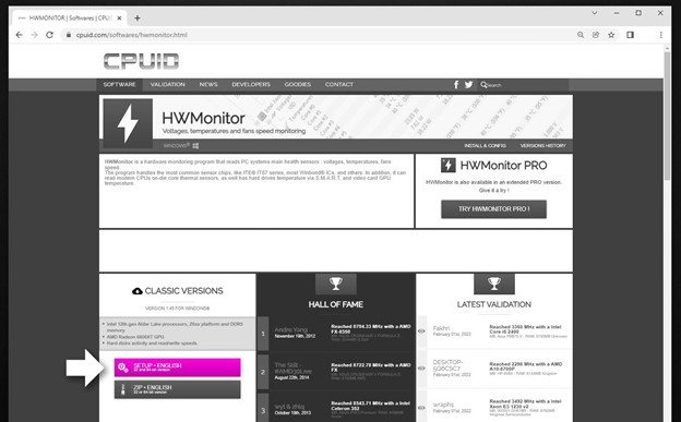
Click on the SETUP ENGLISH button
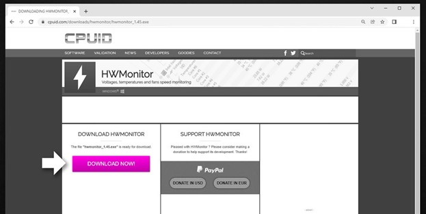
Click on DOWNLOAD NOW! button. This will start the download.
Install and open HW Monitor.
There are a ton of items listed, tab closed everything except the CPU and GPU.
*Note your CPU and GPU will be named differently, look for the little CPU and GPU icons as seen in the below picture.
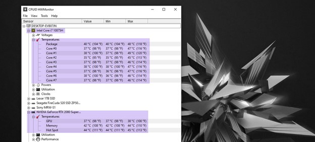
Keep HW Monitor open and run a game. Minimize the game after a few minutes and check your CPU and GPU temps
We are mostly concerned with the CPU temps, but since we worked on the case fans, I always like to be thorough and check GPU temps as well.
Look in the MAX temps column. We want to see Max under 90c ideally between 60-85c for CPU and GPU. This range will vary depending on hardware in your system, ambient room temp and how intensive the game is.

If you notice the CPU shooting up toward 90c, especially within a few minutes of gaming, this indicates there is still some sort of issue with the cooling system.
If you are still having problems with overheating, there may be another issue causing the issue that is more detailed than this guide can address. please contact our technical support staff. They will be happy to assist with getting your computer fully up and running
Please contact one of our support agents to assist you via (Submit Request) or email (support@buildredux.com)